Subdivision, Development & Servicing Bylaw No 7900
Schedule 5 - Supplemental Construction Specifications


CITY OF KELOWNA SUPPLEMENTAL STANDARDS TO THE MMCD SPECIFICATIONS
Schedule 5 is the supplemental construction standards to the Master Municipal Construction Documents (MMCD) and includes:
- Supplemental Construction Specifications, and
- Supplemental Standard Detailed Drawing.
These supplemental construction standards are to be applied in conjunction with the MMCD (Schedule 6) including MMCD Supplementary Updates for Works and Services constructed within the City of Kelowna.
The provisions of the Supplemental Construction Specifications, along with the City’s Approved Products List (APL), Supplemental Standard Detail Drawings and related bylaws, augment and supersede the provisions of the MMCD. The Supplemental Construction Specifications and the Supplemental Standard Detailed Drawings take precedence over the MMCD.
Section and article numbers in the Kelowna Supplemental Standards below coincide with those of the MMCD Specifications. Section Titles with * are complete additional supplemental sections.
1.0 General
(replace 1.0.6)
1.0.6
The City of Kelowna is responsible for issuing Road Usage Permits and conditions set forth, in accordance with Traffic Bylaw No. 8120. The Contractor will be required to obtain a Road Usage Permit prior to work within City Right-of-Way. For projects involving arterial roads, Traffic Control Plans shall be prepared or reviewed and approved by a Professional Engineer with traffic experience or a Professional Traffic Operations Engineer (PTOE). Step by step reference can be found in the "City of Kelowna Traffic Management Guide" at the City’s website kelowna.ca.
1.0.7
In addition to the Public Notice required in Section 01 58 01, the Contractor shall provide additional written notice to residents and businesses one day prior to access closures or restrictions. The content and form of the written notifications shall be reviewed and approved by the Contract Administrator prior to delivery. Emergency, vehicle and pedestrian access to all businesses and residences shall be maintained at all times unless otherwise approved by the Contract Administrator. Suitable access shall have a minimum lane width of 3.0m and be defined as a bladed and comfortable driving surface, free of potholes and other impediments, sufficient to accommodate a standard two-wheel drive passenger vehicles at a speed of 20 km/h.
1.0.8
Working hours are outlined in Good Neighbour Bylaw No. 11500. Requests to vary working hours must be approved in advance, in accordance with the provisions of Bylaw No. 11500.
1.0.9
All regulatory signs that are affected by the work must be removed and replaced by the City of Kelowna in accordance with Traffic Bylaw No. 8120. Requests for sign changes must be made 15 Days in advance of proposed work.
1.2 Temporary Erosion and Sediment Controls
(replace 1.2.2)
1.2.2 Work Adjacent to Watercourses
- Work around watercourses shall be done in accordance with terms and conditions of the Federal, Provincial and Municipal permits and approvals included in the Contract Documents, and the most recent version of the “Land Development Guidelines” published by the Provincial Ministry of Environment.
1.4 Environmental Protection
(replace 1.4.2)
1.4.2 Site Clearing and Plant Protection:
Construct Tree Protection Zones, in accordance with Tree Protection Bylaw No. 8041 and Municipal Properties Tree Bylaw No. 8042. Any tree damage must be reported immediately to the City Engineer.
Protect roots of retained trees during excavation and site grading by ensuring a Tree Protection Zone is maintained and any fallen fencing is repaired immediately. Construction material, soil, and equipment storage is prohibited within Tree Protection Zones.
Temporary access within Tree Protection Zones must be monitored by an arborist or equivalent Qualified Professional to ensure appropriate protection measures (such as 300mm wood chip mulch laid over geotextile fabric, 25mm plywood, or other as dictated by intensity of access) are in place over the root zone prior to temporary access. An arborist must oversee root pruning if excavation in a retained tree root zone is necessary.
Minimize the spread of invasive plant species by cleaning machinery prior to accessing site.
Minimize stripping of topsoil and vegetation.
1.4.3 Pollution Control:
(add)
(5) Ensure proper containment and disposal of concrete wash water.
1.4.4 Spill Contingency Plan:
(add)
Prepare and provide a written Spill Contingency Plan prior to commencement of construction activities.
Spill Contingency Plan shall include the following as applicable:
- Provisions for secondary containment for all stationary bulk fuelling tanks, equipment washing and maintenance areas. Secondary containment for fuelling tanks must be a minimum 110% of the volume of the tank or 40% of the volume of all the containers stored, whichever is the greater volume.
- Spill Kits and protective equipment that include adsorbent pads, booms, etc. for containing and mopping up small spills, and gloves, coveralls, shovels, containers, etc. to use to mop up spilled substances.
- Segregation and disposal procedure (or contingency plan) for contaminated soils and/or contaminated groundwater.
- Reporting procedure that includes “reportable volumes” and numbers to call in the event of a spill. For example, spills of oil or diesel fuel equal to or in excess of 100 L must be reported to the Provincial Emergency Program (PEP) at 1.800.663.3456.
When calling PEP be prepared to answer the following:
- your name and contact phone number;
- name and phone number of the person who caused the spill;
- location and time of the spill;
- type and quantity of the substances spilled;
- cause and effect of the spill, and details of action taken or proposed;
- description of the spill location and surrounding area;
- names of agencies on scene and name of other persons or agencies advised of the spill.
5. Small spills less than 10 L may be dealt with by the Contractor (or sub-contractor) provided equipment is available to contain and clean-up the spilled substances and all soils affected by the soil. Any spill to a surface water or City of Kelowna utility must be reported to the Fire Hall Dispatch at 250-860-8801, or use 911 in any emergency situations where response times are critical.
1.4.5 Work Near Fish Bearing Streams and/or Sensitive Habitats:
(add)
(1) Mitigation measures and best management practices must be employed for work in or near fish bearing streams and/or sensitive habitats in accordance with applicable Municipal, Provincial and Federal regulations.
(2) The Contractor is responsible to ensure all necessary Municipal, Provincial, and Federal approvals have been attained prior to undertaking Work within an Environmentally Sensitive Area, as defined in the Kelowna 2040 – Official Community Plan Bylaw No. 12300.
[NC1]Specifications are typically for contractors, not owners. Requiring them to check that permits have been obtained prior to commencing work is appropriate.
(5) The Contractor shall be responsible for ensuring that they have copies of the City of Kelowna Natural Environment Development Permit and the Provincial Water Act authorization at the work site and are familiar with the requirements
1.5 Temporary Storm Water Pollution Controls
(add)
1.5.1
No person shall discharge or allow or cause to be discharged into a storm drain, any substance except storm water, in accordance with Sanitary Sewer/Storm Drain Regulation Bylaw No. 6618-90. For temporary construction dewatering discharge, a Temporary Discharge Permit must be obtained from the City in accordance with Bylaw No. 6618-90.
1.0 General
1.5 Inspection and Testing
(add)
1.5.2
One (1) compressive strength test (3 field-cured cylinders to ASTM C31M) shall be made for each 150 square metres of concrete work. Minimum one test per batch or per day. The Contractor is to protect cylinders on site, maintaining a temperature of 16-27ºC, for minimum of 16 hours and a maximum of 48 hours, after which they can be sent to the laboratory. One cylinder shall be tested at 7 days and two at 28 days. If tests do not meet specified strength, the Contract Administrator may require additional testing or removal and replacement in accordance with CSA 23.1
3.0 Execution
3.9 Expansion Joints
(delete 3.9.3 and replace with the following):
3.9.3
Expansion joint material is not required for curbs and sidewalks; use bond break compound. Expansion joint material is required in plaza areas as shown on the Drawings and where walks are placed against fixed objects that extend above the walk, such as structures, kiosks or poles, and surrounding stamped concrete truck aprons.
3.0 Execution
3.10 Luminaires and Photocells
(replace 3.10.2)
3.10.2
Install post top and pendant fixtures level. Cobra style fixtures to be installed parallel with the longitudinal grade of the road surface, to reduce glare on the downhill side.
1.0 General
1.3 Approvals
(add)
1.3.5
Crushing and/or screening of granular aggregates shall only be permitted within the project area or on any City of Kelowna road right-of way when specifically approved by the City of Kelowna. Any applications for gravel processing would need to adequately address dust, noise and location/proximity of production in accordance with Zoning and/or Temporary Use Permits.
2.0 Products
2.1 Materials - General
(add)
2.1.3
The physical properties of the materials for Select Granular Subbase and Granular Base course shall meet the following specifications:
| Physical Property | Test Designation | Granular Sub-base | Granular Base |
MgSO4 Loss % Course Ag (Max) | ASTM C88 / C88M | 20 | 20 |
| MgSO4 Loss % Fine Ag (Max) | 25 | 25 | |
| Sand Equivalent % (Min) | ASTM D2419 | 25 | 35 |
| Micro-Deval Loss % (Max) Course Agg. (Max) | ASTM D6982 | 30 | 25 |
| Micro-Deval Loss % (Max) Fine Agg. (Max) | ASTM D6982 | 35 | 30 |
| Plasticity Index % (Max) | ASTM D4318 | 0 | 0 |
| Crushed Particles (one face) % (Min) | MoTI-202 (A) | - | 60 |
| Flat & Elongated Particles (4:1 Ratio) % (Max) | ASTM D4791 | - | 10 |
| Asphalt Coated Particles % (Max) | MTO LS-621 | 30 | 30 |
| Clay and Friable Particles % (Max) | ASTM C142 | 1 | 1 |
| California Bearing Ratio (Soaked) % (Min) | ASTM D1883 | 40 | 80 |
Note: MTO = Ontario Ministry of Transportation
2.7 Granular Pipe Bedding and Surround Material
(replace 2.7.2)
2.7.2
Pit Run Sand as specified in Section 31 05 17 – 2.4 may also be used as pipe bedding and surround material, provided compacted density specification is met or unless otherwise specified by the Contract Administrator
(replace 2.7.3)
2.7.3
Other permissible materials: only where shown on Contract Drawings or directed by the Contract Administrator shall drain rock or approved native material be used for bedding and pipe surround. If native material is approved, warning tape is required.
(add)
2.7.4
A maximum percentage by weight of 30% Reclaimed Asphalt Pavement (RAP) may be uniformly blended with virgin aggregates and used for Type 1 Granular Pipe Bedding and Surround Materials. The maximum size of the RAP material shall be 19mm. Recycled concrete shall not be used as pipe bedding.
2.8 Select Granular Sub-base
(replace 2.8.1)
2.8.1
Granular subbase aggregate shall be composed of well graded granular material capable of withstanding the deleterious effects of water, freeze/thaw, handling, spreading, compacting and the design traffic loading. The aggregate particles shall be uniform in quality and conform to the following gradation:
| Sieve Designation | Percent Passing |
| 150 mm | 100 |
| 100 mm | 85 - 100 |
| 50 mm | 65 - 100 |
| 19 mm | 40 - 100 |
| 4.75 mm | 20 - 70 |
| 0.150 mm | 0 - 20 |
| 0.075 mm | 0 - 8 |
(add)
2.8.2
Maximum aggregate particle size to be no more than 50% of total thickness of sub-base layer.
2.10 Granular Base
(replace 2.10.1)
Granular base aggregate shall be composed of well graded granular material capable of withstanding the deleterious effects of exposure to water, freeze/thaw, handling, spreading and compacting and design traffic loading. The aggregate particles shall be uniform in quality and conform to the following gradation:
| Sieve Designation | Percent Passing |
| 25 mm | 100 |
| 19 mm | 80 - 100 |
| 9.5 mm | 60 - 90 |
| 4.75 mm | 35 - 70 |
| 2.36 mm | 25 - 50 |
| 1.18 mm | 15 - 35 |
| 0.300 mm | 5 - 20 |
| 0.075 mm | 2 - 8 |
2.11 Recycled Aggregate Material
(replace 2.11.1)
2.11.1
Aggregates containing recycled material may be use if approved and certified by the Contract Administrator in consultation with the geotechnical consultant. In addition to meeting all other conditions of this specification, recycled material should not reduce the quality of construction achievable with quarried materials. Recycled material shall consist only of aggregates, crushed Portland cement concrete, or asphalt that is free of impurities.
(replace 2.11.2)
2.11.2
Recycled Concrete and Asphalt (RCA) may be used as subbase or base within the pavement structure and can be used as random fill in the subgrade with the following restrictions:
- Recycled Asphalt Pavement (RAP) content in the RCA shall be limited to a maximum of 30% by weight of the final blended product as determined by test method MTO LS-621 (see Section 2.1.1).
- RCA shall only be placed below areas that will be capped with asphalt concrete, concrete, chip seal or other impermeable surfacing.
- RCA shall not be used for bridge end fill or backfill for retaining walls.
- RCA shall not be stockpiled or doubled handled on the project site without Contract Administrator approval in consultation with the geotechnical consultant.
- RCA shall not be placed within 30 m of drinking water wells/intakes, as measured in a straight line along the ground surface from the edge of the RCA to the water well/intake.
- RCA shall not be placed within 30 m of a designated stream (as defined by the B.C. Water Sustainability Act), as measured in a straight line along the ground surface from the edge of the RCA to the seasonal high-water mark of the stream.
- RCA shall not be placed below the 1 in 200-year flood elevation or the seasonal high-water table elevation.
(replace 2.11.3)
2.11.3
All recycled concrete aggregate shall be at least 28 days or older prior to processing and blending into RCA. The RCA blend shall contain an aggregated weight of less than 1 percent of construction waste and deleterious materials. Construction waste and deleterious materials include reinforcing steel, other metals, expansion material, plastics, rubber, glass, organic materials, brick, mica, schist glass, gypsum, clay and friable materials. Construction waste and deleterious materials excluding clay and friable materials should be visually identified, separated, and removed from the sample for weighing. Testing for the clay and friable material component shall be according to ASTM C142 (see Section 2.1.1) and shall be combined with the weight of the separated and removed materials for final weighing.
(replace 2.11.4)
2.11.4
Prior to the placement of RCA materials, each source of RCA must provide laboratory test results meeting the requirements for physical properties outlined in Clause 2.1.3. On-going, quality control requirements for RCA are as shown in the following table:
| Physical Property | Test Designation | Test Frequency |
| Aggregate Gradation | ASTM C136 | Every 2,500m3 |
| Standard Test Methods for Laboratory Compaction Characteristics of Soil using Standard Effort | ASTM D698 | Every 2,500m3 |
| Standard Test Methods for In-Place Density and Water Content of Soil and Soil-Aggregate by Nuclear Methods (Shallow Depth) | ASTM D6938 | Five random tests per lift for every 2,500 m2 |
| Micro-Deval Loss (%, Max) Course Agg. (Max) | ASTM D6928 | Every 5,000 m3 |
| Micro-Deval Loss (%, Max) Fine Agg. (Max) | Every 5,000 m3 | |
| Asphalt Coated Particles (%, Max) | MTO LS-621 | Every 2,500 m3 |
| Construction Waste, Deleterious Particles, Clay and Friable Materials (%, Max) | ASTM C142 | Every 2,500 m3 |
| Soaked California Bearing Ratio (%, Min) | ASTM D1883 | Every 2,500 m3 |
All samples for testing shall be taken from the stockpile at the location where the RCA is being produced.
1.0 General
1.5 Definitions
(add)
1.5.1
Tree Protection Zone, as identified as a requirement by City of Kelowna Municipal Properties Tree Bylaw (No. 8042), is the area of the site required for the protection of trees, shrubs and understorey vegetation shown on the Contract Drawings and includes the earth beneath the tree protection zone.
1.5.2
Drip Line is the area of ground beneath the outermost branch tips of a tree or shrub.
2.1 Materials
(add)
2.1.10
For material and specifications for construction refer to Municipal Properties Tree Bylaw (No. 8042)
3.1 Existing Trees
(replace 3.1.1)
3.1.1
Inspect with Contract Administrator and clearly identify on site all existing shrubs and trees shown on Contract Drawings to be preserved. Establish Tree Protection Zones (TPZ) around such shrubs and trees and maintain the TPZ barricades, fencing or markings until directed by the Contract Administrator to remove.
(replace 3.1.6)
Water preserved shrubs and trees every week during the growing season or as needed during drought periods, following the advice of a qualified professional irrigation scheduler or certified arborist. Soak area immediately around shrubs and below tree crowns sufficiently deep to reach feeder roots, at minimum to a depth of 30cm.
(add)
3.1.7
Root pruning should only be undertaken under the supervision of a certified arborist. For accidentally severed tree roots greater than 25mm diameter, cut cleanly using a sharp cutting tool to minimize exposed face of cut surface.
3.1.8
Any damage to retained trees must be reported to the Contract Administrator immediately and the tree must be assessed by a certified arborist to determine what repair/protection measures are needed.
3.3 Lowering Grade Around Existing Trees
(replace 3.3.2)
3.3.2
Excavations within a Tree Protection Zone must be supervised by a Certified Arborist.
3.4 Pruning
(add)
3.4.1
Pruning of retained tree, protected tree, or city tree as defined in Bylaw 8041 and 8042 requires a Tree Cutting Permit issued by the City of Kelowna. If hazardous limb removal is deemed necessary, work must be supervised by a certified arborist unless there is an imminent threat to safety.
3.5 Clean Up
(replace 3.5.2)
3.5.2
Replace or provide compensation for any trees the Contract Administrator assesses as irreparably damaged as determined by an Arborist and according to the requirements of the International Society of Arboriculture Guide for Establishing Value of Trees or Other Plants, 1983.
3.6 Tree Zone Protection
(add Sub-Section)
3.6.1
Install barrier prior to clearing, tree removal, grubbing, demolition or alteration of the grade of the site. Tree Protection Zones are needed for any trees to be retained on site or within 10m of the site, as identified by City of Kelowna Parks staff.
3.6.2
Prior to installation of barrier, stake the proposed alignment and location of the barrier and obtain the Contract Administrator’s approval for the same. Adjust the barrier alignment and location as required by the Contract Administrator.
3.6.3
Barriers are not required for those portions of the tree protection zone of trees, shrubs and understorey vegetation located beyond the limit of disturbance shown on the Contract Drawings.
3.6.4
Barriers for tree protection zones that overlap or are in close proximity to each other may be combined to minimize the number of barriers that need to be installed where it is compatible with other Work on the site.
3.6.5
Align the barrier and locate barrier posts outside the limits of the tree protection zone. Braces for the barrier may be located inside the tree protection zone provided they do not impact roots within the zone.
3.6.6
Refer to Municipal Properties Tree Bylaw (No. 8042) for required protection zone sizing.
3.6.7
The type of barrier used to delineate a tree protection zone shall be as follows:
(1) Solid barrier: as required to prevent fill or loose material from entering a tree protection zone.
(3) Flexible barrier: the minimum barrier required for protection of trees, shrubs and understorey vegetation.
3.6.8
The following activities are prohibited within the limits of the Tree Protection Zone:
- Cutting, removing, moving or pruning trees or shrubs.
- Attaching objects, utilities or equipment to trees.
- Alteration of the existing grade by grubbing, fill, excavation, trenching, site grading or growing medium placement.
- Transit, parking or storage of vehicles or equipment.
- Storage of construction materials, fill/soil, or debris.
- Disposal of concrete, paint, petroleum or other liquids.
- Stakes or posts for barriers.
3.6.9
Maintain barriers in an upright position and in a continuous line outside the limit of the tree protection zone until Substantial Performance. Maintain tree protection sign in an upright, readable condition until Substantial Performance.
3.6.10
Submit request for changes to the limits or requirements of a tree protection zone to the Contract Administrator for review and approval prior to alteration of or encroachment into a tree protection zone. The approval shall apply only to the tree protection zone around each specific tree identified in the Contractor’s request, and not to any or all tree protection zones on the site.
3.7 Trenching Near Existing Trees
(add Sub-Section)
3.7.1
Work within a Tree Protection Zone is discouraged. A proposal for any work must be approved by a certified arborist and include details for approved methods of excavation. This proposal must be provided to the Contract Administrator for approval prior to work commencing.
1.0 General
1.7 Disposal
(add)
1.7.2
The deposit or removal of soil on any land within the City is regulated under the Soil Removal and Deposit Regulation Bylaw No. 9612. The Owner or Contractor as the case may be, is responsible to obtain a permit for such deposit or removal pursuant to the provisions of Bylaw No. 9612.
1.11 Inspection and Testing
(add)
1.11.2
As a minimum, the frequency of quality control testing for compaction densities for trench backfill, road subgrade and embankment fill shall be at least one test per 50 linear metres of trench (including services) or lane width, and the number of tests shall vary per vertical depth as follows:
- Trench backfill and subgrade fill 0.6 m depth or less shall include 1 vertical test per 50 m;
- Trench backfill and subgrade fill between 0.6 m and 1.8 m depth shall include 2 vertical tests per 50 m, with vertical test intervals being equally spaced;
- Trench backfill and subgrade fill greater than 1.8 m depth shall include 3 vertical tests per 50 m, with vertical test intervals being equally spaced.
3.0 Execution
3.6 Surface Restoration
(replace (5))
3.6.7 Permanent Pavement Restoration
(5) Restore pavement as detailed on City of Kelowna Supplemental Standard Detail Drawing SS-G5 and the following:
.1 Final asphalt cutting and milling of edges shall be conducted after trench excavation and backfill processes are completed, just prior to paving so that edges are undamaged.
.2 Where the edge of the saw cut or milled asphalt, whichever is wider, extends into the travel lane, it shall be extended to the mid-point of that lane. Where the edge extends past the mid-point of the travel lane, it shall be extended to the far edge of that travel lane.
.3 Where the edge of the saw cut or milled asphalt, whichever is wider, is less than 1.5 m from the lip of gutter or edge of paved shoulder, it shall be extended to the lip of gutter or edge of paved shoulder.
.4 When an area of existing asphalt between two parallel or transverse trenches is less than one third (1/3) of the total area of the proposed paving of the two trenches, plus the area between them (based on the shortest trench), the existing asphalt shall be removed, and the full area paved in conjunction with the paving of the two trenches.
.5 Regardless of the above, if the longitudinal distance between two trenches is less than three (3) metres it shall be removed, and the area paved in conjunction with the paving of the two trenches. The minimum restoration width shall be sufficient for machine paving unless permitted by the City Engineer.
(add)
3.6.8 Concrete curb and sidewalk restoration:
Existing curbs, sidewalks, and driveways shall be reconstructed and reinstated to ensure proper drainage and appearance, to match existing finish. Concrete curb and gutter to be reinstated between control joints. Concrete sidewalk and driveways to be reinstated to nearest panel joint.
1.0 GENERAL
1.9 Inspection and Testing
(add)
1.9.2
The frequency of density tests for embankment fill (subgrade fill) shall be one test per 250 m2 for each 300 mm vertical lift.
3.4 Placing
(add)
3.4.8
Materials shall be placed and compacted in maximum 300 mm vertical lifts unless otherwise approved by the Contract Administrator.
1.0 General
1.11 Inspection and Testing
(add)
1.11.2
The frequency of density tests for subbase shall be at least one test per 150 m2 placed, minimum one per day, and the test interval shall be consistent and evenly spaced along length and width of the Work. For Work that involves roadway, curb and sidewalk, test locations shall be staggered amongst the travelled lanes, curbs, and sidewalks.
1.0 General
1.11 Inspection and Testing
(add)
1.11.2
The frequency of density tests for base shall be at least one test per 150 m2 placed, minimum one per day, and the test interval shall be consistent and evenly spaced along length and width of the Work. For Work that involves roadway, curb and sidewalk, test locations shall be staggered amongst the travelled lanes, curbs, and sidewalks.
2.0 Products
2.1 Materials
(replace 2.1.1)
2.1.1
Asphalt cement: to CGSB-16.3-M90, Grade 80-100, Class A or PG 64-22.
(replace (2))
2.1.3
(2) Gradations to be within limits specified when tested to ASTM D5444.
| Sieve Designation | Percent Passing |
| Lower and Surface Course | |
| 19mm | 100 |
| 12.5mm | 84 - 95 |
| 9.5mm | 73 - 90 |
| 4.75mm | 50 - 75 |
| 2.36mm | 35 - 57 |
| 1.18mm | 25 - 45 |
| 0.600mm | 18 - 34 |
| 0.300mm | 10 - 26 |
| 0.150mm | 6 - 17 |
| 0.075mm | 3 - 7 |
(replace (8))
(8) Micro Deval % Loss: ASTM D6928, Coarse Aggregate: 18 max.
(replace (12))
(12) Crushed fragments (fraction retained on 4.75mm sieve): at least 85% of particles by mass, to have at least 2 freshly fractured faces. Determination of amount fractured material will be in accordance with MoTI Specification I-11, Fracture Count for Coarse Aggregate, Method “B”, which determines fractured faces by mass.
2.2 Mix Design
(replace full section)
2.2.1
The Contractor, at their cost, must retain a Canadian Council of Independent Laboratories (CCIL) certified, independent testing consultant to perform trial mix designs and to submit the job mix formula. The trial mix design must be performed in accordance with the current Asphalt Institute MS-2 and ASTM D6926 (75 blows per face) and must include five (5) separate trial values of asphalt content. The Contractor must pay for trial mix designs and submissions.
2.2.2
Mixes may contain up to 20% of Reclaimed Asphalt Pavement (RAP) without changing binder grade, provided that the properties of RAP material are considered in the trial mix design. Submissions for RAP mixes must contain all data relevant to RAP utilized in the mix design. Use of Recycled Asphalt Shingles (RAS) will not be permitted.
The amount of total AC in the RAP will be calculated as follows:
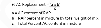
2.2.3
Design of mix: Include the following data with the trial mix design submission:
- Aggregate bulk specific gravity and water absorption.
- Sand equivalent, Micro Deval, Flat and Elongated, Coarse Aggregate Fracture, Fine Aggregate Angularity and Manufactured Fine Content values.
- Asphalt cement properties including mixing and compaction temperatures, based on temperature viscosity properties of asphalt cement.
- A graph of the temperature-viscosity relationship for the asphalt cement.
- Aggregate gradations and blending proportions.
- Maximum theoretical density of trial mixes.
- Asphalt absorption values.
- Information on additives, including source, type, percent by mass of asphalt cement and test results when anti-stripping tests are required.
- Percent Air Voids, Marshall flow, voids in the mineral aggregate, and Marshall stability of the mixture selected.
- Graphs of the air voids, Marshall flow, voids in the mineral aggregate and Marshall stability plotted against asphalt cement content.
- Mix physical requirements to meet Table 2.2.3 below.
- Do not change job-mix without prior approval from the Contract Administrator. Should change in material source be proposed, new job-mix formula to be submitted to the Contract Administrator for review and approval.
| Property | Mix Type |
| Lower and Surface Course | |
| Stability @ 60°C, kN (min) | 9.0 |
| Flow Index, 0.25 mm units | 8 - 14 |
| Voids in Mineral Aggregate % (min) | 14.0 |
| Air Voids, % (2) | 3.0 - 5.0 |
Tensile Strength Ratio, % (min) (3) | 80 |
Notes:
- Percent air voids in compacted trial mixes must be determined in accordance with ASTM D3203, with asphalt cement absorbed into the aggregate compensated for in the calculation.
- In accordance with AASHTO T 283
3.0 Execution
3.1 Plant and Mixing Requirements
(replace (3))
3.1.1 Batch and continuous mixing plants:
(3) Before mixing, dry aggregates to a moisture content not greater than 1.0% by mass or to a lesser moisture content if required to meet mix design requirements.
(9) Where RAP is to be incorporated into the mix:
(add)
(5) RAP shall be introduced such that the RAP is not directly exposed to the flame.
(replace (1))
3.1.4 Mix tolerances including variations resulting from adding RAP:
(1) Permissible variation in aggregate gradation from job mix (percent of total mass):
| (1) | 4.75mm sieve and larger | ± 5 |
| (2) | 2.36 and 1.18mm sieves | ± 4.0 |
| (3) | 0.600mm sieve | ± 3.0 |
| (4) | 0.300mm sieve | ± 2.0 |
| (5) | 0.150mm sieve | ± 1.5 |
| (6) | 0.075mm sieve | ± 1.0 |
3.2 Equipment
(add)
3.2.1
- Pavers must be capable of placing a standard mat width not less than 3 m and must be capable of paving wider widths in 150 mm and 300 mm increments by means of equipment supplied by the manufacturer of the equipment. The screed must include a tamping bar or strike-off device.
- Control of the screed must be by automatic sensing devices. Longitudinal control must be by a sensor that follows a stringline, ski or other reference. The grade sensor must be movable, and mounts provided so that grade control can be established on either side of the paver. A slope control sensor must be provided to maintain the proper transverse slope of the screed.
3.6 Compaction
(add)
3.6.1
Re-rolling of the asphalt will not be accepted as a remedy to increase test that do not meet specifications.
(replace (1))
3.6.2 General
(1) Provide sufficient compaction equipment to ensure that the compaction rate meets or exceeds the placement rate and to ensure that specified density is achieved before the temperature of the mat falls below 100°C.
3.7 Joints
(add)
3.7.1 General
(4) When placing final pavement layer against concrete curb & gutter, compacted pavement must meet the gutter at the same elevation or a maximum of 10 mm above and along the entire lip of the gutter. For reverse grade gutter, compacted pavement must meet the gutter at the same elevation to prevent ponding.
4.0 Compliance with Specifications and Payment Adjustment for Non-Compliance
4.1 General
(add following Sub-Sections)
4.1.1
The Contractor Shall provide a finished product conforming to the quality and tolerance requirements of this Specification. Where no tolerances are specified, the standard of workmanship shall be in accordance with accepted industry standards.
4.1.2
Acceptance of any unit of work area at full payment will occur if there are no obvious defects and the results of asphalt content, pavement density, air voids and thickness meet or exceed specified tolerances.
4.1.3
Unit price reductions will only be applied based on full quality assurance testing in accordance with Table 5.3.4.
4.1.4
The Engineer of Record who provides a letter of professional assurance for asphalt paving must satisfy the requirements of this specification. Quality control and quality assurance documentation must be available upon request. Companion samples taken as part of quality assurance testing must be available upon request by the City Engineer.
4.1.5
Any material or workmanship deficiencies are subject to either a payment adjustment to be paid to the City of Kelowna or removal and replacement. Payment adjustments will be determined by the guidelines in this specification. Removal and replacement will be at the discretion of the City Engineer.
4.2 Aggregate Gradation
4.2.1
When the aggregate fails to comply with tolerances set forth in Section 3.1.4.1 of this specification, the City Engineer will initiate the following action:
(1) When two consecutive gradation analyses identify non-compliance with the specified tolerances, the contractor shall be notified in writing and a third test will be completed.
(2) If the third test indicates aggregate gradation non-compliance, the Contractor must suspend asphalt production and placement until corrective action has been taken and additional testing shows compliance with specified tolerance limits.
4.3 Asphalt Cement
4.3.1
Payment adjustment for non-compliance with the tolerance specified:
| Asphalt Content Deviation from Design % | Payment Adjustment Factor |
| 0.30 or Less | 0.00 |
| 0.31 to 0.40 | 0.30 |
| 0.41 to 0.50 | 0.75 |
| 0..50 or Greater | Remove and replace (at the discretion of the City Engineer) |
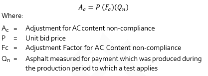
4.3.2
Adjustment for asphalt cement (AC) content non-compliance to the amount payable for Hot Mix Asphalt Paving equals the unit bid price times the payment adjustment factor times the quantity to which the factor is to be applied, i.e.:
4.4 Pavement Thickness
4.4.1
Pavement of any type found to be deficient in thickness by more than 10 mm must be removed and replaced by pavement of specified thickness, at the contractor’s expense.
4.4.2
Pavement of any type found to be deficient by less than 10 percent of its specified compacted thickness will not be subject to payment adjustment for thickness non-compliance.
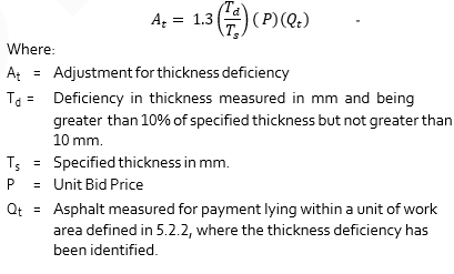
4.4.3
Pavement of any type found to be deficient in thickness by more than 10 percent of its specified thickness but not more than 10 mm shall give rise to an adjustment in the amount to be paid to the Contractor. The adjustment shall be subtracted from the amount otherwise payable to the Contractor, and the amount of the adjustment will be paid to the City. The adjustment shall be calculated as follows:
Note:
No allowance will be made for the tolerance provided for in Section 4.4.2. No payment will be made for additional thickness.
4.5 Density
4.5.1
The minimum specified density for acceptance, without payment adjustment, must be 97% of the 75 blow Marshall bulk relative density as most recently determined by the appointed testing agency.
4.5.2
Payment adjustment for density non-compliance will be as follows:
| Density (% of 75 Blow Marshall Bulk Relative Density) | Payment Adjustment Factor |
| 97 and greater | 0.0 |
| 96.5 to 96.9 | 7.5% |
| 96.0 to 96.4 | 15.0% |
| 95.5 to 95.9 | 22.5% |
| 95.0 to 95.4 | 30.0% |
| Less than 95.0 | No Payment (Note 1) |
Note 1: Subject to removal and replacement at the discretion of the City Engineer.
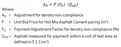
Adjustment for density specification non-compliance shall be determined as follows:
4.6 Adjusted Payments
4.6.1
The total adjustment arising from pavement deficiencies identified in the foregoing shall be determined as follows:
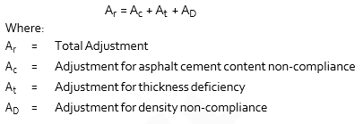
The total adjustment (Ar) shall be applied to the unit price for the quantity of work being accessed.
4.7 Segregation
4.7.1
The finished surface shall have a uniform texture and be free of segregated areas. A segregated area is defined as an area of the pavement where the texture differs visually from the texture of the surrounding pavement.
4.7.2
All segregation will be assessed using ASTM E965. The City Engineer to determine repair requirements.
The severity of segregation will be rated as follows:
Slight - The matrix of asphalt cement and fine aggregate is in place between the coarse aggregate particles, however there is more stone in comparison to the surrounding acceptable mix.
Moderate - Significantly more stone than the surrounding mix and exhibit a lack of surrounding matrix.
Severe - Appears as an area of very stony mix, stone against stone, with very little or no matrix.
4.7.3
Areas of moderate segregation may be left in place for lower courses, subject to approval of the City Engineer, but are considered defective areas for surface course. Areas of severe segregation are considered defective areas for lower and surface courses. Defective areas shall be removed and replaced with acceptable hot mix asphalt of the same type and compacted to the satisfaction of the City Engineer.
4.7.4
Any other methods of repair proposed by the Contractor will be subject to the approval of the City Engineer.
4.7.5
Repairs will be carried out by the Contractor at their expense.
4.8 Smoothness
4.8.1
The completed asphalt concrete surface shall be smooth and true to the established crown and grade. The surface course shall be free from deviations exceeding 5 mm as measured in any direction with a 3 m straight edge.
4.8.2
When deviations more than the above tolerances are found, the pavement surface shall be corrected by methods satisfactory to the City Engineer. Correction of defects shall be carried out until there are no deviations anywhere greater than the allowable tolerances.
5.0 Testing Frequency and Procedures
5.1 General
5.1.1
The City Engineer shall have access to all production processes and materials used for the work to monitor material quality as often as deemed necessary. Such inspection and testing shall not in any way relieve the Contractor of the responsibility for meeting the requirements of this specification.
5.1.2
At least three weeks prior to commencing work, inform the Contract Administrator of the proposed source of aggregates, provide access for sampling, provide equipment to obtain representative samples from stockpiles, and provide samples of asphalt cement in accordance with Section 2.1.1.
5.1.3
The unit of work area considered for acceptance is each 1,500 m2 of continuous paving production. When less than 1,500 m2 is produced in a construction period the actual production for that period may, at the discretion of the Contract Administrator, be added to the previously completed pavement construction.
5.1.4
Minimum testing outlined in Table 5.3.4 must be completed for full payment and acceptance of work.
5.2 Quality Control
5.2.1
Quality control is the responsibility of the Contractor throughout every stage of the project, to ensure that all materials and work conform to the requirements as specified in the Contract Documents.
5.2.2
Reclaimed asphalt pavement (RAP) shall be considered as an aggregate for the purposes of quality control.
5.2.3
All quality control shall be conducted by qualified personnel. The Contractor shall bear the cost of all quality control testing and consulting services.
5.2.4
Quality Control testing, sampling and minimum frequencies are described in Table 5.2.4, Quality Control Requirements.
5.2.5
Pre-Production Quality Control test data as specified in Table 5.2.4 shall be reported to the City Engineer one week prior to commencing the project, or as requested.
| Quality Control Requirements | Test Standards | Minimum Frequency |
| Pre-Production | ||
| Asphalt Cement Certification | - | Once per year or for change in supplier. |
| Aggregate Physical Properties Sec. 2.1.3 | Section 2.1.3 | Once per year, or for change in source. |
Coarse Aggregate, Manufactured Sand, Natural Fines, Blend Sand Aggregates Gradation | ASTM C117 ASTM C136 | One for every 1,000 tonnes of each class of material processed into stockpile, or one analysis for each material every production day when production rate is less than 1000 tonnes. |
| RAP Asphalt Content and Gradation | ASTM D6307 ASTM D2172 ASTM D5444 | One sample per 500 tonnes or a minimum of ten samples per stockpile, whichever amount is greater. |
| Trial Mix Design by Marshall Method | Section 2.2 Asphalt Institute MS-2 | One per mix type every production year, or as required for a change in asphalt cement supply, aggregate gradation or aggregate source. |
| Post-Production | ||
| Hot Mix Asphalt Analysis (including Asphalt Content, Aggregate Gradation, Marshall Bulk Relative Density and Void Properties) | ASTM D6307 ASTM D2172 ASTM D5444 ASTM D3203 | For each mix type one hot mix analysis for every 500 tonnes or one sample per day of paving, whichever is greater. Samples must be taken at the paving location. See Note 1. |
| Compaction Monitoring (Core Density) | ASTM D2726 ASTM D2950 | Minimum Frequency not specified. See Note 2. |
Note 1:
Where an individual test indicates non-compliance, the Contractor must immediately initiate remedial measures, and submit, at its expense, evidence that compliance exists with the approved mix design.
Note 2:
Coring is subject to the approval of the Contract Administrator.
5.3 Quality Assurance
5.3.1
Acceptance of all hot mix asphalt material and paving will be based on the results of Quality Assurance (QA) testing from a lab that is Canadian Council of Independent Laboratories (CCIL) certified.
5.3.2
Quality assurance testing is the responsibility of the Contract Administrator for acceptance of work completed.
5.3.3
Quality Assurance sampling and testing is described in Table 5.3.4, Quality Assurance Minimum Testing Requirements.
5.3.4
Quality Assurance Sampling Procedures:
(1) Loose mix samples shall be acquired from the work site in accordance with ASTM D979. Sampling from the auger can be substituted for this standard provided that no sample segregation is probable. Companion samples must be taken for use as 3rd Party appeal test samples.
(2) The timing of mix sampling shall be stratified, with each sample representing a similar production quantity.
(3) Core locations will be selected using representative random sampling procedures. The unit of work area will be divided into segments meeting or exceeding the minimum frequency in Table 5.3.4 and of approximately equal area. The longitudinal coordinates will have similar spacing on roadway and transverse coordinates will be located using random numbers. Coring locations will be determined in the office prior to sampling, approved by the Contract Administrator. Core sampling requires written approval by the City of Kelowna.
(4) Areas within 5.0 m of transverse joints or 0.5 m of a mat edge are excluded from compaction acceptance sampling and testing.
(5) The Contract Administrator for a private project must be able to provide the opportunity for the City Engineer to sample paving materials when the City of Kelowna deems it necessary.
| Quality Assurance Requirements | Test Standards | Minimum Frequency |
Hot Mix Asphalt Analysis (including Binder Content, Aggregate Gradation, Marshall Bulk Relative Density, Maximum Relative Density, Marshall Stability and Flow and Void Properties) | ASTM D6307 ASTM D2172 ASTM D5444 ASTM D3203 ASTMD6927 ASTM D2041 | For each mix type one hot mix analysis per 1500 m2 or one test per 4.0 hrs of continuous paving, whichever is greater. Companion samples must be taken for use as 3rd Party appeal test samples. |
Compaction Testing (Core Density) and Thickness Determination | ASTM D2726 ASTM D3549 | Three cores per 1,500 m2. Three cores for areas between 500m2 and 1,500m2. Number of tests required for areas less than 500m2 will be at the discretion of the Contract Administrator. |
Hot Mix Asphalt Temperature | - | No minimum frequency |
5.4 Appeal of Quality Assurance Testing Results
5.4.1
The Contractor may appeal the results of acceptance testing for Compaction Standardor Asphalt Content for any area subject to rejection or unit price reduction. The notice of appeal shall be in writing and submitted to the City Engineer within 7 days of receipt of the acceptance testing results.
5.4.2
Appeals will only be considered if a cause can be proven, and the requirements of Table 5.2.4 have been satisfied.
5.4.3
Quality Control tests initiated after the Contractor’s receipt of the Quality Assurance test results will not be considered when evaluating cause for appeal. Heating and remolding pavement cores for the purpose of determining asphalt content, gradation or Marshall volumetric properties is not acceptable.
5.4.4
Only Quality Control testing during production for the subject project will be considered when evaluating cause for appeal provided test results are submitted to the City Engineer prior to the receipt of the acceptance testing results.
5.4.5
Laboratories conducting acceptance testing for appeals must be CCIL certified for the subject test procedures.
5.5 Asphalt Content, Compaction Standard or Air Void Appeals
5.5.1
The testing laboratory conducting the project acceptance sampling and testing will routinely retain companion samples sufficient for the determination of asphalt content, maximum relative density and/or Marshall relative density. Minimum companion sample size should be 10 kg for this purpose.
5.5.2
For asphalt content, compaction standard or air void (Marshall relative density) appeal testing, the Contractor will have the option for the testing to be done by the testing laboratory undertaking the Quality Assurance testing, or an independent testing laboratory selected by the City Engineer. If the independent testing laboratory does not have a valid asphalt correction factor as per ASTM D6307 - Asphalt Content of Hot Mix Asphalt by Ignition Oven the lab should have the capability to perform ASTM D2172 - Quantitative Extraction of Bitumen from Bituminous Paving Mixtures.
5.5.3
The appeal test results will be used for acceptance and unit price adjustment and shall be binding on both the City of Kelowna and the Contractor.
5.5.4
If the new asphalt content, new compaction and/or new air voids content verifies that any unit price reduction or rejection applies for that area of work, the costs of the appeal sampling and testing will be borne by the Contractor. If the results show that a penalty or rejection no longer applies, the sampling and appeal costs will be the responsibility of the City of Kelowna.
5.6 Core Density and Thickness Appeals
5.6.1
Core density and thickness appeals will only be considered if a case can be made that the stratified random sampling plan was biased, or sampling and testing was in error.
1.0 General
1.3 Source Quality Control
(add)
1.3.3
Submit soil analysis results to Contract Administrator minimum 5 Days prior to deliver or placement of growing medium (topsoil). Contractor not to supply or place growing medium and amendments that will not or do not meet the physical and chemical properties described in this Section without the prior written approval of the Contract Administrator.
1.5 Inspection and Testing
(add)
1.5.2
Submit 1.0kg sample of each proposed material and amendment to the Contract Administrator and soil testing laboratory. Independent soil testing laboratory to be approved by the Contract Administrator.
(add)
1.5.3
Have testing laboratory analyse samples for chemical, physical and biological properties specified in this Section, to include pH, lime requirements, soluble salts or electrical conductivity (E.C.), % Sands + % Fines (Silt and Clay) + % Organic Matter = 100%, % Total Nitrogen, and available levels of phosphorous, potassium, calcium and magnesium.
(add)
1.5.4
Have testing laboratory advise on suitability of material for intended use and make recommendations for manufacture and amendment of growing medium to meet requirements of the Contract Documents. Note that the Contract Administrator may accept the soil if it closely meets the requirements, based upon the recommendations of the laboratory.
(add)
1.5.5
Results of laboratory testing to be made available to the City Engineer upon request.
2.0 Products
2.9 Fertilizers
(add)
2.9.2
Chemical fertilizer use must be approved by City Engineer prior to use and should be limited to areas where compost is not available/suitable.
2.9.3
Fertilizer should not be used in restoration.
2.10 Growing Medium
(replace Table 2)
Particle Size (% of dry weight mineral fraction per Canadian System of Soil Classification) | Tree Pits & Low Traffic Lawn Areas | High Traffic Lawn Areas | Planting Beds & Planters | Naturalized Grass | Naturalized Beds |
| Gravel > 2mm | 0 - 5 | 0 - 5 | 0 - 5 | 0 - 10 | 0 - 10 |
| Sand 0.05mm - 2mm | 50 - 70 | 80 - 90 | 50 - 70 | 30 - 70 | 30 - 70 |
| Silt 0.002mm - 0.05mm | 10 - 25 | 5 - 15 | 10 - 25 | 15 - 50 | 15 - 50 |
| Clay < 0.002mm | 0 - 20 | 0 - 5 | 0 - 20 | 15 - 30 | 15 - 30 |
| Silt + Clay | 25 max | 15 max | 25 max | 60 max | 60 max |
| Acidity (pH) | 6.0 - 7.0 | 6.0 - 7.0 | 5.5 - 7.0 | 6.0 - 7.0 | 6.0 - 7.0 |
| Organic Content (% of dry weight) | 3 - 5 | 3 - 5 | 15 - 20 | 5 - 10 | 10 - 15 |
| Drainage | Percolation shall be such that no standing water is visible 60 minutes after at least 10 minutes of moderate to heavy rain or irrigation. | ||||
2.11 Compost
(add sub-section)
2.11.1
Compost to be uniform blend of natural source-separated organic materials, composted such that it is brown-black in colour and has carbon to nitrogen ratio of 25 to 1 or lower and pH 6 to 7. Compost to be substantially free from subsoil, pests, roots, wood, construction debris, undesirable grasses or weeds, and seeds or parts thereof. Compost to be substantially free from toxic materials, crabgrass, couch grass, equisetum, other weeds, and seeds or parts thereof.
2.11.2
Use of compost to be approved in writing by the Contract Administrator prior to mixing or placement.
3.0 Execution
3.4 Placing Growing Medium
(replace 3.4.5)
3.4.5
Place growing medium to minimum depth after settlement specified on Contract Drawings. Where no depth is specified on Contract Drawings place growing medium to minimum depth after settlement specified in Table 3 for Coarse Textured Subsoil to increase water retention.
3.7 Acceptance
(add)
3.7.2
If analysis of placed growing medium indicates that the physical or chemical properties of the material varies from the limits and ranges specified in this Section, the Contract Administrator may do one or a combination of the following:
- Require removal and replacement of growing medium that does not meet the limits and ranges specified in this Section.
- Require the application and incorporation of soil amendments to enable the soil to meet the physical and chemical requirements specified in this Section.
- Accept the work at a reduced price determined by G.C. 9 Valuation of Changes and Extra Work.
3.10 Drainage Control
(add sub-section)
3.10.1
Provide proper water management and drainage of site during construction. Include silt traps, erosion control measures, temporary water collection ditches, as well as maintenance during construction period.
1.0 General
1.0.1
Section 32 91 23S refers to those portions of the work that are unique to the use of soil cells for the planting of trees and landscaping in pedestrian and vehicular areas. This section must be referenced to and interpreted simultaneously with all other sections pertinent to the works described herein.
1.1 Related Work
1.1.1
Concrete Walks, Curbs and Gutters Section 03 30 20
1.1.2
Cast-in-Place Concrete Section 03 30 53
1.1.3
Aggregates and Granular Materials Section 31 05 17
1.1.4
Excavation, Trenching and Backfilling Section 31 23 01
1.1.5
Roadway Excavation, Embankment and Compaction Section 31 24 13
1.1.6
Geosynthetics Section 31 32 19
1.1.7
Granular Base Section 32 11 23
1.1.8
Topsoil and Finish Grading Section 32 91 21
1.1.9
Irrigation System Section 32 94 01S
1.1.10
Planting of Trees, Shrubs and Ground Covers Section 32 93 01
1.2 Mockup
1.2.1
Prior to the installation of soil cell system, construct a mockup of complete installation at the discretion of the Contract Administrator.
1.2.2
Mock up to be a minimum 10m2 in area and to consist of complete soil cell system, including soil cell frames, geogrid, growing medium, soil cell deck and geotextile, all installed in excavation on prepared and approved granular base, geotextile, and subgrade.
1.2.3
Mock up may, upon approval of the Contract Administrator, remain as part of the installed work at end of project if it remains in good condition and meets requirements of Contract Documents. Otherwise, mock-up to be removed at Contractor’s expense.
1.3 Site Conditions
1.3.1
Inspect all areas to receive soil cells prior to placement. Before proceeding with work check and verify dimensions, quantities, grade elevations, drainage, compaction, and contamination.
1.3.2
Report defects in dimensions, quantities, grade elevations, drainage, compaction and contamination to the Contract Administrator immediately and make good to satisfaction of the Contract Administrator prior to construction of soil cell system.
1.4 Delivery, Storage and Handling
1.4.1
Deliver packaged materials in original, unopened containers showing weight, certified analysis and name and address of manufacturer.
1.4.2
Do not handle, deliver or place bulk materials in frozen, wet or muddy conditions. Deliver materials to site at or near optimum compaction moisture content.
1.4.3
Protect excavation from freezing conditions, accumulation of water and contamination until placement of soil cells, growing medium, geotextile and root barrier. Maintain protection of excavation and placed material until installation of hard surfaced roadway or pedestrian surface above.
1.4.4
Growing medium, granular base and backfill that is excessively wet, segregated or contaminated will be rejected. Remove rejected material from site and replace with approved material at Contractor’s expense.
1.5 Layout and Elevation Control
1.5.1
Provide layout and elevation control during installation of soil cells. Utilize grade stakes, benchmarks, surveying equipment and other means and methods to ensure that layout and elevations conform to layout and elevations shown on Contract Drawings.
1.6 Scheduling
1.6.1
Schedule installation of soil cells after all affecting walls, curbs, footings and utility work in the area have been installed. Coordinate schedule with scheduling of other trades on site.
1.7 Measurement and Payment
1.7.1
Payment for soil cells will be made separately for each vertical column of soil cell assembly, and includes all soil cell components, growing medium, site preparation, placement, geogrid and geotextile, protection of work and incidentals. Payment will be made separately for assemblies comprised of one, two or three layers of soil cell frames.
1.7.2
Payment for excavation, backfilling and embankment of soil cells will be made under Section 31 23 01 - Excavating, Trenching and Backfilling or Section 31 24 13 - Roadway Excavation, Embankment and Compaction, as provided in the Schedule of Quantities and Unit Prices.
1.7.3
Payment for placement and compaction of granular base will be made under Section 32 11 23 - Granular Base, as provided in the Schedule of Quantities and Unit Prices.
1.7.4
Payment for pedestrian or vehicle surfaces above soil cells will be made under separate sections as appropriate.
1.7.5
Payment for tree planting, associated non-soil cell growing medium, root barrier, tree grates and concrete surrounds will be made under separate sections as appropriate.
1.8 Inspection and Testing
1.8.1
Refer to General Conditions, Clause 4.12, Inspections and Testing
1.8.2
Refer to Section 32 91 21 - Topsoil and Finish Grading - 1.3 and 1.5.
2.0 Products
2.1 Soil Cells
2.11
Soil cell to be fiberglass-reinforced polypropylene structure, or other materials, designed to support sidewalk loads, designed to be filled with growing medium for the purpose of growing tree roots, and for rainwater filtration, detention and retention.
Acceptable soil cell systems include the following:
(1) Silva Cell by DeepRoot Partners, including:
- Silva Cell frame: 400 x 600 x 1200 mm
- Silva Cell deck: 50 x 600 x 1200 mm, including manufactured installed galvanized steel tubes
- Silva Cell modified: 400 x 600 x 150 mm modified Silva Cell frame designed to stiffen and align frames as growing medium and backfill is placed
- Silva Cell deck screws: manufacturer supplied stainless steel screws to attach decks to frames
(2) Approved Equal.
2.2 Anchor Spike
2.2.1
Galvanized steel spike with spiral twist, 8mm diameter and 250mm length.
2.3 Drainage Pipe
2.3.1
Drainage pipe to be perforated drainpipe per Section 33 40 01 - Storm Sewers - 2.7, as specified on Drawings.
2.3.2
Fittings to be compatible with specified pipe and by same manufacturer.
2.3.3
PVC pipe solvent and primer combinations shall be as recommended by manufacturer and suitable for use with specified materials and application.
2.4 Inspection Riser Assembly
2.4.1
Inspection riser to be 100mm diameter Schedule 40 non-perforated PVC pipe per Section 32 94 01S– Irrigation System. Cut four (4) 3mm wide slots in bottom of pipe that extend to soil cell deck to allow water access for inspection.
2.4.2
Fittings and caps to be compatible with specified pipe and by same manufacturer. Cap to be solid threaded cleanout or removable inlet grate designed to fit inspection riser and be compatible with pedestrian traffic and operational practice.
2.5 Geogrid
2.5.1
Geogrid to be high molecular weight high tenacity polyester multifilament yarns woven in tension and polymer-coated, with the following ASTM D 6637 mechanical properties:
- Tensile strength: 29.2 kN/m
- Creep reduced strength: 18.5 kN/m
- Long term allowable design load: 18.5 kN/m
- Grid aperture size (machine direction): 22.2mm
- Grid aperture size: 25.4mm
- Mass /unit area (ASTM D 5261): 254.3 g/m2
2.6 Geotextile
2.6.1
Geotextile to be non-woven polypropylene fabric, with the following properties:
- Grab tensile strength: 167.8 kg
- Grab tensile elongation: 50%
- Mullen burst strength: 2,620 kPa
- Puncture strength: 58.97 kg
- Apparent opening size: US sieve 80 (0.180 mm)
- Water flow rate: 3,870.8 l/min/m2
- Minimum roll width: 3600 mm
2.7 Granular Base
2.7.1
Granular base and subbase to be as shown on Contract Drawings and to conform to Section 32 11 23 - Granular Base.
2.8 Backfill
2.8.1
Backfill material adjacent to soil cells to be as shown on Contract Drawings.
2.9 Growing Medium
2.9.1
Growing medium to be as shown on Contract Drawings and to conform to Section 32 91 21– Topsoil and Finish Grading.
2.10 Root Barrier
2.10.1
Root barrier to be per Section 32 93 01 - Planting of Trees, Shrubs and Ground Covers - 2.15.
3.0 Execution
3.1 Soil Cell Frame
3.1.1
Confirm that granular base meets compaction requirements of 95% of maximum dry density in accordance with ASTM D698 Standard Proctor method prior to placement of soil cell frame units. Grade sub-base surface on a plane parallel to the proposed finish grade above.
3.1.2
Identify tree openings, utility routes and edges of hard surfaces above soil cells on granular base using spiked string and/or spray paint.
3.1.3
Confirm that width and length of excavation are a minimum of 150mm beyond the edges of the Soil Cells. Layout location of all drain lines. Do not locate drain lines within 150mm of any Soil Cell post. Provide field engineering when drain lines are being installed to assure that the slope on all drains is 1% minimum towards intended outfalls. Place frame units by hand.
3.1.4
Place first layer of frame units on prepared and approved granular base and geotextile. Work away from tree and utility openings. Place frame units no less than 25mm apart and no more than 75mm apart.
3.1.5
Verify that horizontal and vertical position of frame units are consistent with required locations and dimensions of tree and utility openings, paving edges, surfaces and other structures to be constructed above soil cells. Report conflicts to the Contract Administrator and make adjustments as necessary.
3.1.6
Ensure that each frame unit sits firmly on granular base. Ensure frames do not rock or bend over any stone or other obstruction and do not bend into dips in base.
3.1.7
Check each frame unit for damage prior to placing in excavation. Do not use frame units that are cracked or chipped.
3.1.8
Secure soil cell to granular base with four anchor spikes driven through molded holes in base of frame unit.
3.1.9
For applications where soil cells are installed over waterproofed structures, develop a spacing system consistent with requirements of waterproofing system and do not use anchor spikes that will come within 150mm of any waterproofing material. Submit shop drawing of spacing and anchoring system for approval by the Contract Administrator.
3.1.10
Install next layer of frame units on top of previous layer. Build layers as stacks of frame units set one directly over the other. Do not set frame unit half on one unit below and half on another unit.
3.1.11
Register each upper frame unit on top of lower frame unit post. Ensure contact points are free of dirt, mud and debris prior to placement. Ensure each upper unit is solidly seated on unit below. Rotate each frame registration arrow in the opposite direction from frame unit below to ensure connector tabs firmly connect.
3.1.12
Install no more than two layers of frame units before installation of growing medium and backfill.
3.2 Modified Soil Cell Frame
3.2.1
Install modified frame unit on top of frame unit prior to installation of growing medium and backfill. Modified frame unit is required only during installation and compaction of growing medium and backfill.
3.2.2
Remove modified frame unit prior to installation of deck unit and as installation of growing medium and backfill progresses across soil cell framework. Place and remove modified frame units by hand.
3.3 Geogrid
3.3.1
Install geogrid curtain prior to installation of growing medium and backfill.
3.3.2
Geogrid curtain is required between edge of soil cell and any backfill or granular base beyond extent of soil cell framework that will support pedestrian or vehicular paving.
3.3.3
Install geogrid curtain where required. Do not install geogrid curtain between edge of soil cell and any planting area or tree opening adjacent to soil cell.
3.3.4
Pre-cut geogrid to allow for 150mm minimum underlap below backfill, and 300mm minimum overlap above soil cell deck.
3.3.5
Where soil cell layout causes a change of direction in plane of geogrid, slice top and bottom flaps of geogrid and fold so it lies flat on top of soil cell deck and granular base course along both planes.
3.3.6
Provide 300mm minimum overlap between different sheets of geogrid.
3.3.7
Secure geogrid to frame units and deck units with 4.5mm x 300mm plastic zip ties in locations recommended by manufacturer. After deck unit is secured in place fold 300mm overlap of geogrid over top of unit.
3.4 Growing Medium and Backfill
3.4.1
Install root barrier as shown on Contract Drawings. Protect root barrier from damage and displacement during installation of growing medium and backfill.
3.4.2
Install growing medium and backfill as indicated on Contract Drawings. The process of installation requires that these two materials be installed and compacted together in alternating lifts to achieve correct compaction relationships between the materials.
3.4.3
Place growing medium in soil cell framework and spread by hand or hand tool through each soil cell in a maximum 200mm lift. Work soil under horizontal beams of soil cell frame and utility conduit to eliminate air pockets there. Ensure equipment bucket does not contact soil cell framework. Hold plywood sheet against geogrid during placement and compaction of growing medium to protect geogrid and maintain consistent separation of materials.
3.4.4
Finalize installation of utility conduit, drainage pipes and irrigation where shown on Contract Drawings.
3.4.5
Compact growing medium lift by stepping on entire exposed surface of growing medium. Do not step on frame units. Ensure there is a minimum of 250mm of growing medium over horizontal beams of frame units before beginning compaction. Leave top 50mm of frame unit exposed above growing medium to allow placement of next layer of frame units.
3.4.6
Compact growing medium to 85% of standard proctor density. Remove growing medium that is over compacted and reinstall.
3.4.7
Place backfill to 95% of maximum dry density in space between geogrid and sides of excavation and spread by hand adjacent to soil cell framework to provide maximum 200nn lift. Ensure geogrid under lap lays flat under backfill. Ensure equipment bucket does not contact soil cell framework. Hold plywood sheet against geogrid during placement and compaction of backfill to protect geogrid and maintain consistent separation of materials. Do not place backfill material in tree or planting bed opening.
3.4.8
Compact backfill per Contract Documents. Ensure compaction equipment does not contact soil cell frame or deck.
3.4.9
Repeat placement and compaction of growing medium and backfill in lifts to top of topmost frame unit. Finish grade of growing medium to be 25mm below bottom of deck unit, except as indicated otherwise on Contract Drawings.
3.4.10
Do not place final lift of backfill until adjacent deck unit is secured in place. Then install and compact backfill flush with soil cell deck. Ensure compaction equipment does not contact deck unit. Maintain modified frame unit in place until installation of deck unit.
3.5 Soil Cell Deck
3.5.1
Obtain the Contract Administrator’s approval of placement and compaction of growing medium and backfill prior to installation of soil cell deck.
3.5.2
Process for installation of deck units requires that deck units be installed immediately after removal of modified frame units.
3.5.3
Ensure contact points are free of dirt, mud and debris prior to placement. Register deck unit on top of frame unit post. Do not set deck unit half on one frame unit below and half on another frame unit. Ensure deck unit is solidly seated on frame unit.
3.5.4
Snap deck unit onto frame unit using snapping mechanism on corners of deck unit. A rubber mallet may be used to hammer snaps into place.
3.5.5
Secure deck unit corners to frame unit posts using screws provided by manufacturer.
3.6 Geotextile
3.6.1
Place geotextile over top of soil cell deck and where indicated on Drawings. Extend geotextile minimum 450mm beyond outside edge of excavation. Overlap geotextile joints minimum 450mm. Cut geotextile to provide minimum 200mm overlap of tree, planting and utility openings.
3.7 Inspection Riser Assembly
3.7.1
Install inspection riser assembly on top of geotextile in location shown on Contract Drawings immediately prior to placement of granular base. Maintain assembly in fixed position during placement of granular base and final hard surface treatment.
3.8 Geotextile
3.8.1
Supply and install geotextile under soil cell system as shown on Contract Drawings and per Section –31 32 19 - Geosynthetics.
3.8.2
Supply and install geotextile on soil cell deck as shown on Contract Drawings and per Section 31 32 19 - Geosynthetics.
3.8.3
Place geotextile over top of soil cell deck and where indicated on Drawings.
3.8.4
Extend geotextile minimum 450mm beyond outside edge of excavation. Overlap geotextile joints minimum 450mm. Cut geotextile to provide minimum 200mm overlap of tree, planting and utility openings.
3.8.5
Repair cut or damaged geotextile with a second piece of geotextile prior to placement of granular base. Overlap edges of cut or damaged area with second piece by a minimum of 300mm.
3.9 Granular Base
3.9.1
Supply and install granular sub-base course under soil cell system as shown on Contract Drawings and as specified in Section 32 11 23 - Granular Base.
3.9.2
Supply and install aggregate base course above soil cell system as shown on Contract Drawings and as specified in Section 32 11 23 - Granular Base.
3.9.3
Maximum tolerance for deviations in finished surface of granular base for soil cell system is 6mm over a 1200mm distance. Adjust granular base under each frame unit to provide a continuous solid base of support to required grade elevation.
3.9.4
Install granular base course on geotextile immediately after installation of geotextile.
3.9.5
Place granular base on soil cell system from one side of soil cell deck to other, to ensure geotextile and granular base conforms to cell deck contours.
3.9.6
Do not place or spread granular base in several positions at same time.
3.9.7
Load granular base onto soil cell system from equipment located outside limits of soil cell excavated area. Do not drive vehicles or operate equipment directly on top of soil cell deck, geotextile or granular base. Do not drive vehicles or operate equipment greater than 450kg directly on granular base over soil cell deck.
3.9.8
Spread granular base on soil cell system using hand tools or by light use of equipment bucket.
3.9.9
Compact granular base in Iifts not to exceed 150mm, to 95% of maximum dry density. Compact granular base on top of soil cell system using walk behind type vibratory plate tamper, vibratory roller or jumping compacter having a maximum weight of 450kg.
3.9.10
For alternate method of placing and compacting granular base on top of soil cell system (e.g. for large area, small area, area of difficult access) submit shop drawing of proposed equipment and procedure to Contract Administration for approval.
3.10 Protection of Work
3.10.1
Protect soil cell system, geotextile and granular base from vehicles, equipment, other materials and excessive moisture.
3.10.2
Use temporary fencing or hoarding to keep vehicles and equipment away off soil cell area until final surface materials are placed.
3.11 Clean Up
3.11.1
Dispose of surplus materials and all construction debris off site.
2.0 Products
2.1 Plant Material
(replace (12))
2.1.2
(12) All trees and plants to be inspected by the Contract Administrator and the City Representative upon delivery to site.
(add)
(13) Container stock #3 and less is to be considered small; and container stock #5 and up is to be considered large as specified on Table 3 in Section 32 92 21 Topsoil and Finish Grading.
(add)
2.1.3
Submit written requests for plant material substitutions to the Contractor Administrator for review within 20 Days of receiving Notice to Proceed. Provide explanation for substitution and evidence the plant material is not available within 400km of the site.
2.4 Mulch
(replace 2.4.1)
2.4.1
Mulch to be ‘Glenmore Grow’ or ‘Ogogrow’ as determined by the Contract Administrator, obtained from City of Kelowna Landfill Operations (location to be confirmed), and shall be free of all soil, stones, sticks, roots or other extraneous matter. Depth after settlement as specified.
2.5 Stakes
(replace 2.5.1)
2.5.1
Stakes to be as shown on Contract Documents. Where not otherwise shown on Contract Documents, stakes to be pressure treated wood 50-70mm diameter approximately 2.0m long.
2.6 Guying Collar
(replace 2.6.1)
2.6.1
Acceptable products for guying collars and tree ties include the following:
- Deep Root ArborTie series
- Approved Equal
2.13 Tree Rings, Grate, Frames, Guards and Boxes
(add)
2.13.1
Tree rings, grates, frames, guards and boxes to be as shown on Contract Documents. Where not otherwise shown on Contract Documents tree rings, grates, frames, guards and boxes to be per Shop Drawing approved by the Contract Administrator.
2.14 Root Barrier
(add)
2.14.1
Depth and length of root barrier product to be as shown on Contract Drawings. Acceptable root barrier products include the following:
- Deep Root UB series
- Approved Equal
1.0 General
1.0.1
Section 32 94 01S refers to those portions of the work that are unique to the complete or partial installation or repair of an automatic underground irrigation system, including all necessary preparatory work and all electrical, wiring and plumbing connections, and maintenance work during the guarantee period.
1.0.2
This section applies to General Contractors and Sub-Contractors for all services and sites that will be maintained by City of Kelowna staff. This section must be referenced and interpreted simultaneously with all other MMCD (Master Municipal Construction Document) sections pertinent to the works described herein. Where standards in this document exceed those in MMCD, these standards shall take precedence.
1.1 Related Work
1.1.1
Project Record Documents Section 01 33 01
1.1.2
Cast-in-Place Concrete Section 03 30 53
1.1.3
Precast Concrete Section 03 40 01
1.1.4
Aggregates and Granular Materials Section 31 05 17
1.1.5
Site Grading Section 31 22 01
1.1.6
Excavating, Trenching and Backfilling Section 31 23 01
1.1. 7
Topsoil and Finish Grading Section 32 91 21
1.1.8
Hydraulic Seeding Section 32 92 19
1.1.9
Seeding Section 32 92 20
1.1.10
Sodding Section 32 92 23
1.1.11
Planting of Trees, Shrubs and Ground Covers Section 32 93 01
1.1.12
Waterworks Section 33 11 01
1.2 References
1.2.1
Abbreviations referenced within this document with respect to testing, materials, fabrication and supply are fully described in References - Section 01 42 00.
1.2.2
Installation of irrigation components near trees must meet City of Kelowna tree protection Bylaws 8041 and 8042.
1.3 Codes and Permits
1.3.1
Perform all work of this section in strict accordance with all municipal, provincial, or federal guidelines, regulations, and codes. Requirements of these specifications not conflicting therewith, exceeding code requirements govern.
1.3.2
Contractor is responsible for obtaining all necessary permits and approvals required to undertake and complete the work.
1.4 Quality Assurance
1.4.1
Provide documentation in writing of minimum of 5 years of industry experience and a member in good standing of at least one of the following organizations:
- Irrigation Industry Association of British Columbia (IIABC)
- The Irrigation Association (IA)
1.4.2
If the irrigation design involves High Density Polyethylene (HPDE) pipe, all welds required during project construction must be done by an HDPE installer who holds a current training certificate from a recognized HDPE training organization to weld and install HDPE pipe. Provide documentation to the Contract Administrator.
1.4.3
All electrical components or products specified or used in construction of the proposed irrigation system must be CSA approved and installed in accordance with the most recent versions of the Safety Standards Act and Electrical Safety Regulation.
1.4.4
Install all irrigation components per manufacturer’s instructions and specifications.
1.4.5
All materials to be new and without flaws.
1.4.6
Attend a mandatory pre-construction meeting with City of Kelowna Parks Department Representative.
1.5 Definitions
1.5.1
Journeyman Plumber is an individual who: (i) holds a Certificate of Qualifications; (ii) follows the BC Plumbing Code; (iii) is governed by the local plumbing authority; (iv) and is responsible for all required permits and inspections.
1.5.2
Certified Electrician is an individual who: (i) holds a Certificate of Qualifications; (ii) follows the BC and Canadian Electrical Code; (iii) is governed by Technical Safety BC; (iv) and is responsible for all required permits and inspections.
1.5.3
Contract Administrator is a person or company appointed by the City of Kelowna and identified in writing to the Contractor to be the City of Kelowna’s representative for the purposes referenced herein.
1.5.4
City of Kelowna Parks Department Representative is a person designated by the City of Kelowna Parks Department to represent the City of Kelowna Parks Department at project meetings, tests and inspections.
1.5.5
Owner means the City of Kelowna. Where project action or involvement are required, the Owner’s representative will be the City of Kelowna Parks Department Representative.
1.6 Scheduling
1.6.1
Ensure that sequencing of irrigation work is carried out in coordination with the work of other trades and that sleeving, conduit, wire, pipes, valves and other equipment are installed to minimize disruptions.
1.6.2
Plan, schedule and execute work to ensure water is available for landscape establishment and maintenance purposes at the appropriate time, volume, and operating pressures to ensure irrigation is delivered in accordance with plant water needs.
1.7 Substitutions
1.7.1
Where materials are specified by brand name, model number, and/or size, such specifications facilitate a description of the materials and material quality and establish a standard for performance and quality against which proposed substitutes will be evaluated.
1.7.2
Proposed substitutes will match specified materials in quality, performance, flow parameters and pressure loss so as to not compromise the intent of the design or overall performance of the irrigation system.
1.7.3
Proposed substitutes and Shop Drawings; as necessary per the requirements set out below; will be submitted to the Contract Administrator and the Contract Administrator will obtain approval from the City of Kelowna Parks Department Representative.
1.7.4
Proposed substitutions must be submitted to the Contract Administrator at least 10 days before the Tender Closing Date for consideration as an approved equal during the tender period.
1.7.5
Substitution requests by Contractor will have no impact on the Milestone Dates.
1.7.6
Purchase or installation of materials that are not specified will not be paid for unless:
(1) The materials have been reviewed and approved by Contract Administrator and the City of Kelowna Parks Representative as an Approved Equal as per Section 7.0, Instructions to Tenderers, or
(2) The materials have been reviewed and approved by Contract Administrator and the City of Kelowna Parks Representative as a Change Order, per Section 7.3 of the General Conditions.
1.7.7
Installation of materials that are not specified or are not an Approved Equal will be removed and replaced with the specified material at Contractor’s expense.
1.7.8
Where a revision is required to the irrigation system design that will markedly alter the original design, Shop Drawing(s) must be submitted to the Contract Administrator.
1.7.9
After contract award, proposed substitutions must be submitted to the Contract Administrator within 5 days of Notice to Proceed.
1.8 Irrigation Record Drawings
1.8.1
Further to Schedule 3, maintain accurate scaled records of installed irrigation system and its components on a marked-up set of Contract Drawings on a daily basis during construction. Show all deviations from Contract Drawings. Make marked-up Contract Drawings available to the Contract Administrator and/or designated site inspector upon request.
1.8.2
Prepare Record Drawings showing the as-installed location of all irrigation system components including but not limited to, sprinklers, valves, grounding point(s), points of connection, controllers, wire splice boxes, valve boxes, vaults, mainlines, lateral lines, irrigation sleeves. Identify each zone numerically, complete with precipitation rate and US gpm per zone.
1.8.3
Provide Record Drawings in digital AutoCAD (2020 or newer) and Adobe pdf hard copy sized Per project requirements and one laminated drawing in Arch B or Ansi B.
1.9 Operating Manual
1.9.1
Provide one digital copy of the Operating Manual for irrigation system. Content of Operating Manual to include:
- Copies of plumbing permit, electrical permit, HDPE certification.
- Electrical Inspection Request Form and final approval.
- Copies of irrigation inspection reports and test results signed by the individual who presided over the inspection or test.
- Product warranty statement for controllers, meters, backflow prevention assemblies, valves, filters, sensors, electronic components, and related irrigation components. Date warranty with date of issuance of the Certificate of Substantial Performance.
- Written guarantee for work completed, for a minimum of 1 year to commence from the issuance of the Certificate of Substantial Performance.
1.10 Submittals
1.10.1
Submit complete set of Record Drawings to Contract Administrator prior to issuance of Certificate of Substantial Performance.
1.10.2
Submit complete digital copy of Operating Manual to the Contract Administrator and City of Kelowna Parks Representative prior to issuance of Certificate of Substantial Performance.
1.11 Measurement for Payment
1.11.1
Point of Connection: Unless otherwise specified in the Schedule of Quantities and Prices, payment for supply and installation of irrigation point of connection will be measured as a lump sum. The work includes:
- Permits & fees.
- Supply, installation and testing of the connection to the water service line and booster pump.
- Water meter.
- Backflow prevention assembly.
- Hydrometer.
- Blowout assemblies.
- Pressure regulating valve.
- Filters.
- Fittings.
- Vaults, valve boxes & lids.
- Excavation, trenching, conduits, backfill and restoration.
- Inspections and testing.
- All incidentals necessary for the proper installation and operation of a complete irrigation point of connection including water supply to the irrigation point of connection and irrigation system.
1.11.2
Electrical Service: Unless otherwise specified in the Schedule of Quantities and Unit Prices, payment for supply and installation of electrical service will be measured as a lump sum. The work includes:
- Permits & fees.
- Supply, installation and testing of the connection to the electrical source.
- Electrical meter.
- Excavation, trenching, conduits, backfill and restoration.
- Inspections and testing.
- All incidentals necessary for the proper installation and operation of a complete electrical service to the irrigation system.
1.11.3
Control System: Unless otherwise specified in the Schedule of Quantities and Unit Prices, payment for supply and installation of control system will be as a lump sum. The work includes:
- Permits & fees.
- Supply, installation, testing, programming, and adjustment of irrigation system controller(s).
- Transmitters, decoders & communication cartridges
- Electrical conduits.
- Controller kiosk(s).
- Vaults, splice boxes & lids.
- Fittings.
- Excavation, trenching, backfill, and restoration.
- Inspections and testing.
- All incidentals necessary for the proper installation and operation of a complete irrigation control system.
1.11.4
Pipes, valves, sprinklers and micro irrigation: Unless otherwise specified in the Schedule of Quantities and Unit Prices, payment for supply and installation of pipes, valves and sprinklers and micro irrigation components will be measured as a lump sum. The work includes but is not limited to:
- Supply, installation, testing and adjustment of irrigation pipe.
- Supply, installation, testing and adjustment of irrigation dripline.
- Sleeves and conduit.
- Zone control valves.
- Control wire, common wire, flow sensor wire and spare wires.
- Drain valves.
- Isolation valves.
- Air/vacuum relief valves.
- Pressure regulators.
- Swing joint assemblies.
- Sprinklers.
- Root watering systems.
- Emitters and bubblers.
- Fittings
- Valve boxes & lids.
- Excavation, trenching, backfill and restoration.
- Inspections and testing.
- All incidentals necessary for the proper installation and operation of a complete irrigation system.
1.11.5
Post Construction Submittals: Unless otherwise specified in the Schedule of Quantities and Unit Prices, payment for Record Drawings and Operating Manual will be measured as a lump sum.
1.12 Tests and Inspections
1.12.1
Refer to General Conditions, Clause 4.12, Tests and Inspections.
1.12.2
During construction, inspection and testing of components will be required to ensure performance of irrigation system meets expected standards.
1.12.3
Provide equipment and personnel necessary for performance of inspections and tests.
1.12.4
As a condition of issuance of Certificate of Substantial Performance confirm in writing to the City of Kelowna Parks Department Representative, at least one week prior to application for Substantial Performance, that the following inspections and tests have been successfully completed:
- Layout Inspection
- Vault drainage test
- Irrigation Point of Connection Inspection
- Backflow Prevention Assembly Test per BCWWA (British Columbia Water Works Association)
- Mainline pressure test
- Open trench inspection
- HDPE pipe strap test
- Two-wire System Grounding Inspection
- System coverage test
- System operation test
- Dripline/emitter test
- Substantial Performance inspection
1.12.5
Total Performance inspection will be completed after Substantial Performance inspection.
1.12.6
Conduct all inspections and tests in the presence of Contract Administrator. Provide minimum 3 days (72 hours) notice to the Contract Administrator to attend all inspections and tests. Contract Administrator must invite City of Kelowna Parks Department Representative to all tests within 24 hours of receiving the invitation from the Contractor.
1.12.7
The Contract Administrator will ensure that results of that test or inspection are provided to the City of Kelowna Parks Representative within 48 hours of completion.
1.13 Layout Inspection
1.13.1
Conduct Layout Inspection prior to commencement of irrigation system installation. project construction.
1.13.2
Coordinate location of irrigation components with landscaping, building and physical features of site.
1.13.3
Layout and stake irrigation system per Drawings to confirm:
- Layout is within project boundary and property lines.
- Minimum horizontal and vertical clearances from electrical and other utilities are met.
- Location of all sleeving, supply piping, kiosks, vaults, valve boxes, sprinkler heads and splice boxes and other irrigation components match Contract Drawings.
1.14 Vault Drainage Test
1.14.1
Plug drain hole, fill point of connection vault with water to a depth of 300mm and leave water to drain.
1.14.2
Test is passed if water drains in 1 hour or less.
1.14.3
If test is failed, Contractor to rectify drainage issues and organize secondary inspection.
1.14.4
Supply photo of drain pit installation to Contract Administrator.
1.15 Point of Connection Inspection
1.15.1
Verify installed components are per Approved Products List and in accordance with Drawings.
1.16 Backflow Prevention Device Test
1.16.1
Backflow Prevention Test will be conducted prior to commencement of irrigation system operation..
1.17 Mainline Pressure Test
1.17.1
Mainline Pressure Test to be conducted as follows:
- Allow minimum 48 hours from the last glue joint or fusion weld for sections that will be tested.
- Install pressure gauge on the second blowout assembly in the Point of Connection vault.
- Fill mainline with water until all air is expelled from mainline and system has been charged to operating pressure.
- Maintain water in pipe for 4 hours.
- Record initial pressure reading. Record and report any variance greater than 5% from beginning to end of test.
1.17.2
Test results are based on the difference in recorded pressures at beginning and end of test. Passed test is 5% or less drop in pressure from beginning pressure reading to ending pressure reading.
1.17.3
If test is failed, identify source of leak and replace any and all defective materials and workmanship as necessary to eliminate leak.
1.17.4
Repeat mainline pressure test and make replacements as necessary until a passed result is achieved.
1.18 Open Trench Inspections
1.18.1
Open Trench Inspection(s) will be conducted throughout construction schedule.
1.18.2
Contractor to ensure that a minimum of 50% of mainline and 50% lateral pipelines inspected prior to burial.
1.18.3
Inspections are to determine if pipe layout, pipe depth, joining procedures, wiring, bedding material and caution tape placement are in accordance with Drawings.
1.18.4
Contractor to rectify any issues which limit successful completion of inspection and organize secondary inspection if necessary.
1.19 HDPE Weld Inspections and Testing
1.19.1
HDPE Weld Inspections are to be conducted a minimum of three times during project installation. HDPE welds must meet requirements per ASTM F2620.
1.19.2
Conduct minimum of one HPDE weld strap test prior to installing pipe within trench.
1.19.3
Ensure HDPE welding equipment meets requirements per Plastic Pipe Institute Technical Report TR-33 and ASTM F2620.
1.19.4
If a visual or tactile inspection indicates a substandard weld, a strap test of said weld will be required.
1.19.5
Pipe strap test protocol is as follows:
- Conduct visual or tactile inspection of several welds. Where bead does not roll back correctly and/or is not consistent in height or width, the Contractor will perform the strap test.
- At the welded join selected, Contractor to cut fusion weld from pipe, allowing 8” (200mm) on either side of the weld to work with.
- Cut pipe lengthways through fusion weld to create a strap 1” (25mm) wide.
- Bend strap back on itself. If weld breaks repeat test on another fusion weld, chosen by Contract Administrator. If second weld fails the Contractor Administrator may request that all welds be investigated at the expense of the Contractor.
- If fusion weld does not break then weld is acceptable and no further pipe strap testing is required.
1.20 Two-Wire System Grounding Inspection
1.20.1
Two-wire System Grounding inspection to be conducted as per installed two-wire system manufacturer’s requirements.
1.21 System Coverage Test
1.21.1
System Coverage Test will be conducted as part of the Substantial Performance Inspection, after installation and operation of complete irrigation system and prior to issuance of Certificate of Substantial Performance.
1.21.2
Conduct visual inspection to confirm that:
- Head spacing does not exceed that shown on Drawings.
- Heads, valve boxes, vaults and trenches are flush with finished grade.
- Heads and valves have been installed as per the Drawings.
1.21.3
Conduct operational tests to verify that:
- Performance provides head-to-head coverage or meets approved design parameters.
- Minimal overspray occurs onto different zones, hard surfaces or other improvements and/or the spray patterns meet approved design parameters.
1.22 System Operation Test
1.22.1
System Operation Test will be conducted as part of the Substantial Performance inspection, after installation and operation of complete irrigation system and prior to issuance of Certificate of Substantial Performance.
1.22.2
Conduct operational tests to verify that:
- Controller can be programmed manually on site and remotely via Owner’s central irrigation control system.
- Each zone can be operated automatically and in succession via programmed controller.
- Operating pressure is within design parameters.
- Hydrometer readings at controller are within +/-5% accuracy of design flows for all zones.
- Controller flow readings are within +/-5% of the hydrometer flow readings for all zones.
1.23 Dripline/Emitter Test
1.23.1
Dripline/emitter Test will be conducted while all dripline and/or emitter zones are exposed.
1.23.2
Perform inspection and testing of dripline/emitter manifold and lines to identify potential leaks and confirm manifold, driplines and emitters are able to operate at design pressure. Conduct inspection and testing prior to backfilling of manifold, driplines or emitter supply lines.
1.23.3
Verify that dripline / emitter layouts are in accordance with Drawings.
1.23.4
Charge and maintain manifold and lines with water at operating pressure. While charged, visually inspect manifold, driplines and fittings for leaks and replace any and all defective materials and workmanship as necessary to eliminate leak.
1.23.5
Repeat inspection and testing and make replacements as necessary until further leaks are identified.
1.24 Substantial Performance inspection
1.24.1
Substantial Performance inspection is to verify that the installation has reached a point where the Certificate of Substantial Performance can be awarded, and that the installation has met the requirements of these specifications.
1.24.2
Substantial Performance Inspection will include 1.21 System Coverage Test and 1.22 System Operation Test.
1.24.3
Inspection of all plant material to ensure that impacted existing plant material and new material are healthy and in satisfactory growing condition.
1.25 Total Performance Inspection
1.25.1
Total Performance inspection is to verify that any outstanding deficiencies identified during the testing and inspection processes set out within these specifications, have been rectified.
2.0 Products
2.1 Water Service and Meter
2.1.1
Unless already installed or otherwise required by the water utility having jurisdiction over the site provide a metered water service, including but not limited to:
- Plumbing permit.
- Establishment and verification of water account with appropriate utility provider.
- Supply and installation of water meter and backflow prevention assembly; installed in accordance with requirements of the water utility.
2.1.2
Type and size of water meter to be as specified by the water utility having jurisdiction over the site.
2.2 Electrical Service and Meter
2.2.1
Unless already installed or otherwise required by the electrical utility having jurisdiction over the site provide a metered electrical service, including but not limited to:
- Electrical permit.
- Electric meter.
- Establishment and verification of electrical account with appropriate utility provider.
2.2.2
Type and size of electrical service to be as specified on Contract Drawings.
2.2.3
Electric meter to be supplied and installed per standards and specifications of electrical utility.
2.3 Isolation Valve
2.3.1
Per Approved Products List.
2.4 Air Relief Valve
2.4.1
Per Approved Products List.
2.5 Hydrometer
2.5.1
Per Approved Products List.
2.6 Hydrometer Air Relief Vent
2.6.1
Per Approved Products List.
2.7 Hydrometer Communication Cable
2.7.1
Per Approved Products List.
2.8 Pressure Reducing Valve
2.8.1
Per Approved Products List.
2.9 Backflow Prevention Device
2.9.1
Per Approved Products List.
2.9.2
Reduced Pressure Backflow Assembly (RPBA) as per approved design.
2.10 Vault and Lid
2.10.1
Vault and matching lid as per Approved Products List.
2.10.2
Lid must have recessed hinges and locking hardware.
2.11 Ground Assembly
2.11.1
Ground assembly to consist of CSA and BC Electrical Code endorsed products per irrigation controller manufacturer’s recommendations for grounding.
2.12 Irrigation Controller
2.12.1
As specified on Contract Drawings.
2.13 Decoder
2.13.1
As specified on Contract Drawings.
2.14 Controller Kiosk and Base
2.14.1
Per Approved Products List.
2.15 Electric Control Valve
2.15.1
Per Approved Products List.
2.16 Electric Control Valve; Low Flow
2.16.1
Per Approved Products List.
2.17 Filter
2.17.1
Per Approved Products List.
2.18 Quick Coupler Valve
2.18.1
Per Approved Products List.
2.19 Swing Joint Assembly
2.19.1
Fabricated with three threaded Schedule 40 PVC street elbows and one threaded Schedule 80 PVC nipple.
2.19.2
Length of nipple to be sufficient to permit installed head or valve to be set as per Drawings.
2.19.3
Diameter of nipple to match inlet for valve or head shown on Drawings.
2.20 Lateral Flush Assembly
2.20.1
Per City of Kelowna Detail Drawing.
2.21 Valve Box
2.21.1
Per Approved Products List.
2.21.2
Valve box and overlapping matching lid and extensions will be commercial grade and green in colour.
2.22 Control Wire
2.22.1
Conventional system: Control wire from irrigation controller to electric control valve to be minimum #14 gauge, direct burial, type TWU-40 wire. Control wire to be any colour other than white, blue or red.
2.22.2
Conventional system: Common wire from irrigation controller to electric control valve to be minimum #12 gauge direct burial, type TWU-40 wire. Common wire to be white in colour.
2.22.3
Conventional system: Hydrometer wire from the controller to the hydrometer solenoid to be minimum #14 gauge direct burial, type TWU-40 wire. Wire to be red in colour.
2.22.4
Conventional system: Spare control wire to be blue in colour.
2.22.5
Conventional system: Spare common wire to be white in colour.
2.22.6
Decoder system: Two-wire (dual conductor) control wiring to match controller brand.
2.22.7
Wire connectors to be new, two-step, CSA approved for watertight applications and assembled according to the manufacturer’s recommendations.
2.23 Wire Spice Box
2.23.1
Wire splice box as per Approved Products List.
2.24 Irrigation Sleeve
2.24.1
Schedule 40 PVC pipe for irrigation sleeves under hard surfaces.
2.24.2
Irrigation sleeve diameter to be minimum 4” (100mm) or twice the diameter of the pipe running through it; whichever is greater.
2.24.3
System wire conduit to be a minimum 2” (50mm) diameter electrical conduit.
2.25 Polyvinyl Chloride (PVC) Pipe
2.25.1
Must conform to CSA B137.3-93.
2.25.2
Must be new and without flaws, extruded from virgin, high impact materials, solvent weldable with belled ends, continually and permanently marked showing manufacturer’s name, material, size, pressure rating, and CSA approval.
2.25.3
Pipe series and size as specified on Contract Drawings.
2.26 Polyethylene (PE) Pipe
2.26.1
Must be new and without flaws, CSA Series 100, MDPE (Medium Density Polyethylene), extruded from virgin materials, continually and permanently marked showing manufacturers name, material, size, and pressure rating.
2.26.2
Pipe series and size as specified on Contract Drawings.
2.27 High Density Polyethylene (HDPE) Pipe
2.27.1
Must be new and without flaws, CSA approved, continually and permanently marked showing manufacturers name, material, size, and pressure rating.
2.27.2
Acceptable HDPE pipe is dependent on operating pressure and to have minimum Standard Dimension Ratios (SDR) as follows:
(1) Maximum pressure 160 psi: DR11
(2) Maximum pressure 200 psi: DR9
2.28 PVC and PE Fittings
2.28.1
Must be new and without flaws.
2.28.2
Fittings for PVC pipe systems must be PVC in composition and intended for use with PVC pipe for either solvent welding applications or threaded connections.
2.28.3
Threaded nipples are to be Schedule 80 PVC.
2.28.4
Where pipe changes from metal to PVC pipe, the metal end of the pipe must be a female adapter and the PVC fitting must be a Schedule 80 nipple.
2.28.5
Fittings for PE pipe must meet ASTM D2609 standards, complete with stainless steel gear clamps.
2.29 HDPE Fittings
2.29.1
Must be new and without flaws.
2.29.2
Must be UL or ULC approved.
2.29.3
Butt fusion fittings for use on HDPE must meet ASTM F2206 Standard Specification and be designed for butt fusion welding to HDPE pipe.
2.29.4
Electrofusion type fittings for use on HDPE must meet ASTM F1055 Standard Specification and be designed for electrofusion welding to HDPE pipe.
2.29.5
SDR rating of HDPE fittings must match the SDR rating of the HDPE pipe specified.
2.29.6
HDPE pipe fittings to be moulded or fabricated by a pipe manufacturer. HDPE pipe fittings and flange adapters made by contractors, sub-contractors or distributors are prohibited.
2.29.7
Use of mechanical fittings on HDPE is prohibited unless approved in writing by City of Kelowna Parks Representative.
2.30 Pipe Solvent Cement and Primer
2.30.1
Per Approved Products List.
2.31 Vault Pipe and Fittings
2.31.1
Vault pipe and fittings shall be brass, stainless steel or HDPE.
2.31.2
Brass piping must be in new condition and conform to NSF/ANSI 372.
2.31.3
Stainless steel piping must be in new condition, must be Type 304L or 316L and must conform to ASTM A312.
2.31.4
Selected material for pipe and fittings must be consistent throughout vault.
2.31.5
All pipe and fittings must meet BC Plumbing Code requirements for use with potable water.
2.32 Thrust Block
2.32.1
Thrust blocks shall adhere to MMCD Section 33 11 01 Item 3.13 and MMCD Standard Detail Drawing W1.
2.33 Sprayhead Sprinkler
2.33.1
Per Approved Products List.
2.34 Rotary Sprinkler
2.34.1
Per Approved Products List.
2.35 Dripline
2.35.1
Per Approved Products List.
2.36 Drip Emitter /Bubbler
2.36.1
As specified on Contract Drawings.
2.37 Root Watering Systems
2.37.1
Per Approved Product List.
2.38 Bedding and Backfill Sand
2.38.1
Pit run sand, 2mm or less, per MMCD Section 31 05 17.
2.39 Drain Rock
2.39.1
Drain rock per MMCD Section 31 05 17.
2.40 Bolts
2.40.1
All bolts used in system construction to be stainless steel 304 or 316.
3.0 EXECUTION
3.1 Existing Conditions
3.1.1
Report existing conditions at variance with Contract Drawings to Contract Administrator. Contract Administrator to report information to City of Kelowna Parks Representative.
3.1.2
Verify locations of underground utilities prior to commencing excavation and conduct work so to prevent interruption and damage to services and utilities. Make good all damages to same at Contractor’s cost.
3.1.3
Verify location of all services in building walls before boring or drilling holes. Make good all damages to same at Contractor’s cost.
3.1.4
Protect existing conditions and completed work from disturbance during Work. Make good all damages to same at Contractor’s cost.
3.1.5
Proposed adjustments to installation of irrigation system to avoid existing conditions, completed work and utilities will be permitted subject to prior approval by the Contract Administrator.
3.2 Excavation
3.2.1
Excavate to ensure depth and bedding requirements are met.
3.2.2
All excavation is unclassified. Report any material or site condition that cannot be excavated by normal mechanical or manual means or that may affect excavation to required depth to the Contract Administrator.
3.2.3
Identify and recycle all suitable materials recovered during construction.
3.2.4
Remove and dispose of buried debris exposed during excavation, including decommissioned irrigation materials and underground utility components.
3.3 Water Service
3.3.1
Verify that the provided wate service meets irrigation design requirements as indicated on the irrigation design.
3.3.2
Notify Contract Administrator if the water service provided does not meet design requirements as indicated on the irrigation design and await notice to proceed or other instructions.
3.3.3
Ensure connection to supplied water service meets City of Kelowna Subdivision Bylaw, MCCD Platinum Edition, applicable American Water Works Association standards and BC Plumbing Code.
3.4 Electrical Service and Account
3.4.1
Within 5 Days of receipt of Notice to Proceed provide Contract Administrator with information necessary for Owner to make application to electrical utility for service connection.
3.4.2
Certified electrician or FSR to obtain permits and approvals necessary to install and operate irrigation system.
3.4.3
Coordinate with electrical utility to confirm the availability, suitability, and location of an acceptable service connection.
3.4.4
Install all electrical connections in accordance with local, provincial and national electrical codes.
3.4.5
Ensure grounding is included on electrical permit.
3.5 Water Meter
3.5.1
Install water meter per approved Drawings and requirements of water utility.
3.5.2
Where a water meter is not being installed at the time of construction, install spacers and unions sufficient to allow for the future installation of a correctly sized water meter.
3.6 Isolation Valve
3.6.1
Install isolation valve per Contract Drawings.
3.7 Hydrometer
3.7.1
Install Hydrometer in location specified on Contract Drawings.
3.7.2
Follow manufacturer’s instructions for installation.
Air relief valve is to be installed on the first blowout, threaded into the ball valve or gate valve depending on size of the vault. It is to be used during start-up, once system is charged ball or gate valve can be closed with air relief vent attached. Remove during winterization process.
3.7.3
Install hydrometer drain valve prior to installation. Hydrometer drain valve to be supplied by City of Kelowna Parks Department.
3.7.4
Where system utilizes a conventional wiring layout, communication wire to be PE39 cable; no substitutions permitted. No splices are permitted on the wire path from controller to hydrometer.
3.7.5
Where system utilizes two-wire technology, communication from controller to hydrometer to be as per manufacturer’s specifications.
3.8 Pressure Reducing Valve
3.8.1
Prior to installation, confirm in writing from the City of Kelowna, if a Pressure Reducing Valve (PRV) is required to be installed in the Point of Connection to stabilize pressure/flow.
3.8.2
Install PRV per manufacturer’s instructions in location shown on Drawings and as required to maintain operating pressure within manufacturer’s recommended range.
3.8.3
Adjust PRV to provide water at design pressure.
3.9 Backflow Prevention Device
3.9.1
All backflow prevention assemblies must be installed by Journeyman Plumber carrying required cross connection certification and in accordance with BC Plumbing Code.
3.9.2
Double Check Valve Assembly (DCVA) to be installed within lockable vault.
3.9.3
Reduced Pressure Backflow Assembly installation will require drawing approval by the Building and Permitting Department of the water purveyor in the jurisdiction of installation.
3.9.4
Install backflow prevention assemblies with positive drainage and room for maintenance and servicing.
3.10 Irrigation Vault and Lid
3.10.1
Install vault(s) in location shown on Contract Drawings.
3.10 2
Support and brace point of connection components, piping and valves within vaults using adjustable aluminium pipe stands complete as per Approved Products List in the quantities indicated below:
- 1” to 4” (25-100mm) 3 supports
- Larger than 4” (100mm) as per Drawings
3.10.3
Install irrigation vault drain and connect to drain pit, dry well, manhole or catch basin.
3.10.4
Drainage pit dimensions will match the depth, width and length of the vault installed.
3.10.5
Extend selected piping for POC outside the vault a minimum of 300mm.
3.10.6
Ensure no vault is installed within 200mm of any hardscape.
3.11 Ground Assembly
3.11.1
To meet BC Electrical Code requirements.
3.12 Irrigation Controller
3.12.1
Install approved irrigation controller in approved irrigation kiosk.
3.12.2
Install approved irrigation controller to allow controller door to open sufficiently for full access to control components.
3.12.3
Install approved irrigation controller wiring in accordance with local, provincial and national electrical codes.
3.12.4
Where applicable, install and test the ground assembly using a “Megger” to ensure earth resistance to ground does not exceed controller manufacturer’s recommendations.
3.12.5
Install communication components per manufacturer’s instructions. Establish communication between controller and Owner’s central irrigation control system, including relays as specified by designer.
3.12.6
Operate Controller through 1 year warranty period for plant establishment. Include 1 year warranty period irrigation schedule in Operating Manual.
3.13 Irrigation Kiosk, Antenna and Kiosk Base
3.13.1
Install Irrigation Kiosk (Kiosk), Antenna and Kiosk Base per Contract Drawings.
3.13.2
Provide electrical service to Kiosk as shown on Contract Drawings.
3.13.3
Where dedicated electrical meter is required, install electric meter in the Kiosk per electrical utility’s requirement.
3.13.4
Install one duplex 120v GFI receptacle, on dedicated breaker, in Kiosk.
3.14 Electric Control Valve
3.14.1
Install in valve box per Contract Drawings.
3.14.2
Identify Electric Control Valve with permanent label or tag indicating zone number of valve.
3.15 Filters
3.15.1
Install as per Contract Drawings.
3.16 Quick Coupler Valve
3.16.1
Install as shown on Contract Drawings.
3.16.2
Do not install Quick Coupler Valves in same valve box as electric control valve.
3.17 Swing Joint Assembly
3.17.1
Fabricate assembly of triple swing joint using three threaded Schedule 40 PVC elbows and one threaded Schedule 80 PVC nipple.
3.17.2
Install swing joint assembly to rotate clockwise when depressed.
3.17.3
Tape threads of PVC fittings with Teflon tape and make hard hand tight.
3.18 Lateral Flush Assembly
3.18.1
Install Lateral Flush Assembly on swing joint assembly in valve box per Contract Drawings.
3.18.2
Coil hose in valve box.
3.19 Valve Box
3.19.1
Install all manual and electric control valves, control zone kits and quick coupler valves in valve boxes or concrete vault as shown on Contract Drawings.
3.19.2
Do not install valve boxes in hardscapes.
3.19.3
Install valve box flush with finish grade and arrange in a neat and orderly manner.
3.19.4
Valve box must not contact irrigation pipe. Use matching valve box extensions as required.
3.19.5
Up to three 1” (25mm) control valves or two 1½” (38mm) control valves may be contained within a single valve box provided there is 4” (100mm) of clearance between valves. Install valve 2” (50mm) and larger in their own valve box.
3.20 Control Wire
3.20.1
Install control wire per code and by qualified personnel employed by the company holding the electrical permit.
3.20.2
Bury control wire per applicable code.
3.20.3
Bed control wire in sand with minimum 3” (75mm) sand around control wire. Where control wire is in same trench as pipe, place wire beside pipe (not directly above) with horizontal clearance of a minimum of 3” (75mm) and in accordance with BC Electrical Code depth.
3.20.4
Bundle multiple lengths of wire in same trench or conduit with ties at maximum 10’ (3m) intervals.
3.20.5
Install wire with minimum 24” (600mm) length of coiled slack at all changes of direction, in wire splice boxes and at connections to controlled components.
3.20.6
Identify all control wires entering controller kiosk with permanent label or tag indicating zone number of valve operated by each control wire.
3.20.7
Maintain consistent wire colour through wire splice box.
3.20.8
Minimize wire splices. Where wire splices are unavoidable make splice only in wire splice box using specified connector.
3.20.9
Identify spliced wire with permanent label or tag indicating zone number of spliced control wire.
3.20.10
Provide one spare control wire to for every five (5) electric valves shown on Contract Drawings. Location of spare control wires as per Contract Drawings.
3.20.11
Provide 24” (600mm) length of coiled slack of each wire end in wire splice box. Identify spare control wires as ‘spare’ wire with permanent label or tag.
3.20.12
Provide minimum two spare common wires. Location of spare common wires as per Contract Drawings.
3.20.13
Where the system is a two-wire system, approved two-wire must be as specified by the manufacturer of the controller utilized and installed as per Contract Drawings.
3.21 Wire Splice Box
3.21.1
Locate wire splice box in planting bed where possible and locate for ease of access, maintenance, and testing.
3.21.2
Install wire splice box per Contract Drawings.
3.21.3
Do not install valves in wire splice box.
3.22 Irrigation Sleeve
3.22.1
Install irrigation sleeves in locations shown on Contract Drawings.
3.22.2
Install irrigation sleeve to depth as follows:
- Mainline Piping
- 24” (600mm) below walkways
- 36” (915mm) below driveways, roads and plazas
- Lateral Piping
- 18” (450mm) below walkways
- 36” (900mm) below driveways, roads and plazas
3.22.3
Install sleeve to extend 20” (0.5m) past edge of hard surface into soft landscape surface.
3.22.4
Cap sleeve with removable plug or cover. Maintain plug in sleeve until such time as pipe or wire is ready to be installed.
3.22.5
Bed sleeve as follows:
- Under walkways, 4” (100mm) of sand placed all around.
- Under driveways, roads and plazas, compacted base aggregate all around per materials shown on Contract Drawings.
3.22.6
Bury ½” (12mm) width rebar piece beside each end of sleeve to enable location of sleeve end by metal detector after burial. Rebar piece to be positioned so that the top of the regard is 6” (150mm) below finished grade.
3.22.7
Record location of sleeve ends and label size of sleeve on Record Drawings.
3.23 Pipe and Fittings
3.23.1
Verify that all pipe, fittings, and connecting materials or equipment are compatible for proper installation.
3.23.2
Minimum and maximum burial depth and clearances for pipe and wire are as per Drawings and in keeping with applicable codes.
3.23.3
Nearest side of trench is not to be closer than 12” (300mm) from hard surface or feature.
3.23.4
Keep inside of pipe and outside of pipe ends clean at all times. Cap or plug open pipe ends to keep out dirt and debris.
3.23.5
Follow manufacturer’s instructions and standards for installation of all pipe and fittings.
3.23.6
Follow manufacturer’s instructions and standards for installation of pipe and fittings; minimize excess runoff.
3.23.7
Allow sufficient space between fittings to facilitate future repairs. There shall a be minimum of two times pipe diameter or 2” (50mm) distance between fittings, whichever is greater.
3.23.8
Adhere to HDPE Certification standards and requirements for installation of HDPE pipe and fittings.
3.23.9
Flush irrigation pipe fully to remove accumulation of dirt and debris prior to installation of heads, dripline, emitters and filters. Flush lateral lines to prevent clogging of screens, nozzles and emitters.
3.23.10
Follow manufacturer’s recommendations to allow for expansion and contraction of pipe in trench.
3.23.11
Set mainlines and laterals with 3” (75mm) sand on sides and bottom and 3” (75mm) sand above.
3.23.12
Ensure lateral lines are not installed directly above mainline.
3.23.13
For pipe in landscaped areas backfill trench to depths as per Detail Drawings and tamp in lifts to achieve compaction equal to the adjacent growing medium.
3.23.14
For pipe in native soil, sub-surface fill, rocky soils and aggregate base or sub-base material backfill remainder of trench with suitable non-sand material under 1” (25mm) in diameter and free of materials that could result in settling or damage to pipe or surface improvements.
3.23.15
Install thrust blocks at all changes in direction of PVC pipe 3” (75mm) in diameter or greater, and for any change in direction of gasketed pipe.
3.23.16
Cut pipe ends at right angle to pipe length. Clean burrs prior to joining pipe and fittings.
3.23.17
Do not join pipe or fittings under wet or muddy conditions.
3.24 Thrust Block
3.24.1
Thrust block installation to adhere to MMCD Section 33 11 01 Item 3.13 and Standard Detail Drawing W1.
3.25 Sprinklers
3.25.1
Install per manufacturer’s recommendations and in location shown on Contract Drawings.
3.25.2
Location of heads as illustrated on Contract Drawings is intended as a guide to layout of heads. Establish actual head locations in the field to ensure complete and adequate coverage of all areas to be irrigated and minimal overspray onto adjacent surfaces and improvements. Do not exceed head spacing shown on Contract Drawings.
3.25.3
Where obstructions or site improvements hinder or block head to head coverage advise the Contract Administrator and determine best method to maximize coverage.
3.25.4
For head adjacent to hard surface or improvement set head 2” (50mm) from hardscape as shown on Contract Drawings.
3.25.5
For flat surfaces install head plumb to finished grade. For sloped surfaces install head perpendicular to half the grade of the slope.
3.25.6
Mount pop-up heads on triple swing-joint assembly. Connect bottom inlet of sprinkler to swing joint assembly. Side inlet connection not permitted. Adjust swing joint assembly to set head flush with finish grade.
3.25.7
Adjust sprinklers to achieve head to head coverage of area to be irrigated, with minimum or no overspray onto other surfaces.
3.26 Dripline
3.26.1
Install per manufacturer’s recommendations in location shown on Contract Drawings.
3.26.2
Ensure approved filtration is installed.
3.26.3
Do not install driplines of different flow rates on the same zone.
3.26.4
Place dripline on prepared surface. Surface to free of sharp rocks or other objects that may damage dripline. Surface to be at grade necessary for dripline to be at specified depth after placement of remainder of topsoil or growing medium.
3.26.5
Placement of dripline by trenching using hand or mechanical methods permitted only if specified as such on Contract Drawings or upon written approval of the Contract Administrator.
3.26.6
Do not drive or operate equipment over exposed dripline.
3.26.7
Thoroughly flush each zone after installation and before beginning regular operation of drip zone.
3.27 Drip Irrigation for Planting Beds
3.27.1
For dripline in planting bed stake dripline using manufacturer’s recommended stakes at 18” (450mm) on centre.
3.28 Drip Irrigation for Turf Areas
3.28.1
Install per manufacturer's instructions and as shown on Contract Drawings.
3.29 Emitter/Bubbler
3.29.1
Install per manufacturer’s recommendations and as shown on Contract Drawings.
3.29.2
Install approved filtration per manufacturer's instructions and as shown on Contract Drawings.
3.30 Root Watering System
3.30.1
Install as shown on Contract Drawings.
3.30.2
Root watering system to be installed equidistant, complete with sock and pea gravel.
3.31 Hose Bib
3.31.1
Install as shown on Contract Drawings
3.31.2
Do not install Hose Bibs in same valve box as electric control valve.
3.32 Clean-up and Restoration
3.32.1
Remove and properly dispose of all waste and debris resulting from irrigation installation from site.
3.32.2
Restore all disturbed surfaces to original condition and repair all trench settlement.
3.33 Instructions to Owner
3.33.1
Schedule on-site meeting to instruct City of Kelowna Parks Representative in complete operating and maintenance procedures for irrigation system, including start-up, winterization, and programming.
3.33.2
Review Record Drawings and Operating Manual with City of Kelowna Parks Representative on site.
3.34 Maintenance – General
3.34.1
Inspect, operate, maintain and adjust irrigation system through the one-year guarantee period for construction until issuance of Certificate of Acceptance to ensure it operates as intended, including but limited to:
- Adjust irrigation program to ensure health and growth of the plant material and respond to changes in soil conditions and seasons for site.
- Clean sprinkler heads and adjust coverage to eliminate over watering, under watering and overspray onto adjacent surfaces.
- Monitor and clean filtration equipment.
- Restore grass areas, planting beds, hard surfaces and improvements affected by trench settlement and erosion.
- Respond to requests from the Contract Administrator for program adjustments, servicing, adjustments and repairs.
- Provide digital documentation to the Contract Administrator of any repairs related to vandalism.
3.35 Maintenance – Winterization
3.35.1
During one-year guarantee period for construction, be responsible for winterization of irrigation system at end of growing season and prior to onset of air temperatures below 0º Celsius. Be liable for any damage resulting from late or improper winterization.
3.35.2
Conduct winterization in the presence of the Contract Administrator. Provide minimum 3 days (72 hours) notice to the Contract Administrator to attend. Contract Administrator must invite City of Kelowna Parks Department Representative to winterization within 24 hours of receiving the invitation from the Contractor.
3.35.3
Winterization includes but is not limited to:
- Saturation of soil with water to a depth of 300mm to provide deep watering of all lawn areas, planting beds and tree pits.
- Deactivation of water supply.
- Deactivation of controller.
- Contact City of Kelowna Parks Department to determine if any components within the point of connection are to be removed prior to winterization and if there are specific guidelines to be followed for winterization of the point of connection.
3.36 Maintenance – Spring Start-up
3.36.1
During one-year guarantee period for construction be responsible for spring start-up of irrigation system at beginning of growing season or within 5 Days of request for start-up from Owner. Be liable for any damage resulting from late or improper start-up.
3.36.2
Conduct spring start-up in the presence of the Contract Administrator. Provide minimum 3 days (72 hours) notice to the Contract Administrator to attend. Contract Administrator must invite City of Kelowna Parks Department Representative to Spring start-up within 24 hours of receiving the invitation from the Contractor.
3.36.3
Spring start-up includes but is not limited to:
- Activate water supply slowly and provide location for air to escape prior to charging lines.
- Checking and testing for leaks.
- Cycling irrigation control program through all zones to ensure proper function and performance.
- Checking and adjusting heads and emitters to achieve even coverage with minimum over spray onto other surfaces.
- Testing of backflow prevention assembly. Submit test results to Contract Administrator and place test results tag on the backflow prevention assembly. Test tag must be firmly attached to the tested assembly and include the following information in waterproof ink: Name of Owner, Test Date, Tester initials, Tester Certification Number.
- Saturation of the soil with water to a depth of 12” (300mm) to provide deep watering of all lawn areas, planting beds and tree pits.
3.37 Guarantee
3.37.1
Submit written guarantee, in approved form, stating that all work showing defects in materials, workmanship or operation will be repaired or replaced at no cost to Owner for a period of one year from date of Substantial Performance.
3.37.2
Guarantee includes the supply of labour, materials and equipment necessary for the repair and replacement of damaged or defective materials and workmanship. Guarantee includes Spring start-up, winterization, maintenance, necessary testing, program corrections or adjustments and restoration of settled trenches, valve boxes, and sprinkler heads. Guarantee includes flow sensing verification.
3.37.3
Guarantee will not apply to materials or workmanship damaged after Substantial Performance by causes beyond the Contractor’s control, such as vandalism or abuse.
2.0 Products
2.2 Mainline Pipe, Joints and Fittings
2.2.1 Ductile iron pipe:
(add)
(3) Wrap: Ductile iron pipe and fittings to be installed with a polyethylene encasement conforming to AWWA C104, unless suitable testing of the soil conditions indicate that there is no risk of accelerated corrosion, as approved by the Water Utility Representative.
2.2.4 Fittings:
(replace (8) Bolts and nuts: )
(1) Bolts to be UNC rolled threaded, high-strength low-alloy stainless steel to AWWA C111/A21.11 / ASTM F593, type 304, heavy hex style. Bolt sizes to AWWA C110.
(2) Nuts and washers: nuts to be high-strength low-alloy stainless steel to AWWA C111/A21.11 / ASTM F594, type 304, heavy hex style. Washers to be flat hardened stainless steel, type 304, equivalent to ASTM F436/F436M.
(replace (9) Tie Rods and Nuts: )
(1) Tie rods to be continuous threaded, quenched and tempered high-strength low-alloy stainless steel, equivalent to ASTM A354 , Grade BC. Tie rod sizes to be minimum 19 mm diameter or greater as shown on Contract Drawings.
(2) Nuts and internally threaded couplings to be high-strength low-alloy stainless steel to AWWA C111/A21.11 / ASTM F594, type 304, heavy hex style.
2.5 Service Connections, Pipe, Joints and Fittings
(replace 2.5.1)
2.5.1
Pipe diameter 25 mm and 50 mm to be Pressure Class 160 polyethylene tubing certified to CSA B137.1, or crosslinked polyethylene pipe certified to AWWA C904.
(replace 2.5.5)
2.5.5
Copper tubing joints to be compression type suitable for 1100 KPa working pressure.
2.6 Hydrants
(replace 2.6.2)
2.6.2
Colour: All hydrants are to be painted in accordance with the City Standard Drawing SS-W4 and the Approved Products List.
2.7 Underground Service Line Valves and Fittings
(add)
2.7.5
Curb stops for 50mm services to be accessed by a valve box similar to mainline valves.
2.10 Joint Wrapping
(add section)
2.10.1
As listed in the Approved Products List.
3.0 EXECUTION
3.6 Pipe Installation
(add)
3.6.1
All pipe to be delivered from manufacturer with weatherproof plugs/bagging to prevent contamination while being delivered and during storage. Pipe to remain this way until placed into trench and installed.
(replace 3.6.6)
3.6.6
Do not exceed 50% of the maximum joint deflection recommended by the pipe manufacturer. Refer to AWWA C600 for ductile iron pipe and AWWA C605 for PVC pipe. PVC pipe deflections achieved by bending the barrel are not permitted. For PVC pipe deflections exceeding 50% of manufacturer’s recommendation, use:
- PVC High Deflection coupling rated at 1380kPa (100mm-300mm)
- PVC long radius 5 degree bend rated at 1620kPa (100mm-750mm).
(add)
3.6.15
Marking tape labelled WATERWORKS and tracer wire is to be placed above all pipes at a depth of 0.45m below finished grade in statutory rights-of-way and any other locations where pipe alignment is irregular, as required by the City Engineer.
3.10 Service Connection Installation
(add)
3.10.13
Decommissioning of existing services that are no longer required shall be completed as indicated on the Contract Drawings. Requirements depend on the age, size, and material of the main and service, as well as the ability to shut down the main. Curb stops and valve boxes are to be removed. The options to decommission at the main are as follows:
- Removal of the corporation stop and/or saddle. Once completed a repair clamp is to be installed over the service location. The watermain will need to be shut down during decommissioning.
- If the saddle is in good condition, cap the corporation stop by installing a solid plug behind the flare/compression nut or adapt to a solid cap. After installation, the corporation stop must be opened and closed to confirm no leakage. Abandonment saddle may need to be installed over the corporation stop where it has been direct tapped.
- If the water service was connected to the water main with a flange, then a blind plate is required on the tee, service valve must be removed. The watermain will need to be shut down during decommissioning.
Contractor to coordinate with City of Kelowna representative and Contract Administrator for witnessing of decommissioning work.
3.12 Hydrants
(replace 3.12.6)
3.12.6
For hydrants not in service, place an orange bag over the entire hydrant, secured at the bottom with tape and labelled in black “Not In Service”. Isolation valve to remain closed until the hydrant is put into service. Remove bag and open valve once the water main has been accepted by the Contract Administrator. If the hydrant valve is connected to a live water main, the valve to be operated only by Water Utility staff.
(add)
3.12.7
Prior to putting hydrant into service, Contractor to complete flow testing and submit hydrant data in the form required by the City of Kelowna.
3.14 Corrosion Protection
(add)
3.14.2
All bolts, tie rods and nuts to have petrolatum paste and tape applied.
3.19 Testing Procedure
(add)
3.19.8
Hydrant flow testing to be completed in accordance with the AWWA Manual of Water Supply Practices, Installation, Field Testing & Maintenance of Fire Hydrants (M17).
3.20 Disinfection, General
(add)
3.20.3
Disinfect and flush water reservoirs and appurtenances in accordance with AWWA C652.
3.21 Disinfection and Flushing Procedures
(add)
3.21.10
Flush water main and dispose to a suitable location as approved by the Contract Administrator. If disposing to the storm system or any other environmental sensitive area, dispose to a tanker truck or holding facility and dechlorinate the disinfection solution using Ascorbic Acid (Vita-D-Chlor). Confirm that the solution has been neutralized prior to disposing to the approved disposal location.
(add)
3.21.11
Results from the disinfection procedure must be documented by the Contract Administrator and include actual concentration levels at 0 & 16 hours from both ends of the pipe, in accordance with AWWA standards.
(add)
3.21.12
Test water main in accordance with AWWA C651 to confirm that no bacteria exist. Testing to include two consecutive sets of samples at least 16 hours apart, taken at both ends of the pipe, including all branches and at intervals in between as specified in AWWA 651. Tests required for the samples are Total Coliform, Fecal Coliform, Background Bacteria, and a Chlorine Residual.
(add)
3.21.13
The Contract Administrator to provide the following to the City of Kelowna Water Utility with “Form 6, Request for Connection to the City Water System”. Contact [email protected].
- Copies of all test results including those from other companies that performed any of the tests.
- A sketch or copy of a drawing showing the sections tested and the location of the tie-in(s).
(add)
3.21.14
If the pipe is left idle for a period of more than 1 month, the line is to be re-flushed. Zero hour and 16 hour bacteria samples are to be taken. Repeat flushing and testing until water quality is satisfactory.
(add)
3.21.15
Contractors are expected to keep minimum chlorine residual within the pipe until sufficient demand is connected to the system. Newly constructed water mains without demand are not included in the City’s ongoing watermain flushing program until the one year warranty period expires.
3.23 Connections to Existing Mains
(add)
3.23.2
Make connection (or disconnection) in presence of the City Utility Personnel. Provide two full working days notice to schedule inspection. Obtain and authorize a City Third Party Work order prior to connection (or disconnection). Contractor is responsible to pay for tie-in inspections. The cost will be doubled when witnessing after hours or on weekends.
3.0 Execution
(add)
3.6 Pipe Installation
3.6.14
Marking tape labeled SANITARY SEWER and tracer wire is to be placed above all pipes at a depth of 0.45m below finished grade in statutory rights-of-way and any other locations where pipe alignment is irregular, as required by the City Engineer.
3.12 Leakage Testing General
(remove (5))
3.12.1
Short Term Deflection Test is not required.
3.18 Video Inspection
(replace 3.18.1)
3.18.1
The Contractor shall video inspect completed sanitary sewers and service connections (main to IC) following completion of installation per Section 33 01 30.1 – CCTV Inspection of Pipelines. Copies of the digital video files and written report shall be forwarded to the Contract Administrator as soon as they are available.
3.20 Connection to Existing Mains
(add)
3.20.3
Make connection (or disconnection) in presence of City Utility Personnel. Provide two full working days notice to schedule inspection. Obtain and authorize a City Third Party Work order prior to connection (or disconnection). Contractor is responsible to pay for tie-in inspections. The cost will be doubled when witnessing after hours or on weekends.
2.0 Products
2.2 Pipe, Joints and Fittings
2.2.1
Ductile iron pipe:
(delete 2.2.1 -ductile iron pipe not permitted for forcemains)
2.2.2
Polyvinyl Chloride (PVC) pressure Pipe:
(add)
(4) Forcemain pipe color is to be white.
2.3 Valves and Valve Boxes
2.3.2
Gate Valves:
(delete 2.3.2 – gate vales not permitted for forcemains)
3.0 EXECUTION
3.6 Pipe Installation
(add)
3.6.11
Marking tape labeled SANITARY FORCEMAIN and tracer wire is to be placed above all pipes at a depth of 0.45m below finished grade in roads and statutory rights-of-way and any other locations where pipe alignment is irregular, as required by the City Engineer.
3.16 Connection to Existing Mains
(add)
3.16.3
Make connection (or disconnection) to mains and manholes in presence of City Utility Personnel. Provide two full working days notice to schedule inspection. Obtain and authorize a City Third Party Work order prior to connection (or disconnection). Contractor is responsible to pay for tie-in inspections. The cost will be doubled when witnessing after hours or on weekends.
3.0 Execution
3.6 Pipe Installation
(add)
3.6.14
Marking tape labeled STORM SEWER and tracer wire is to be placed above all pipes at a depth of 0.45m below finished grade in statutory rights-of-way and any other locations where pipe alignment is irregular, as required by the City Engineer.
3.12 Inspection and Testing
(replace 3.12.1)
3.12.1
The Contractor shall video inspect completed storm sewers, catchbasin leads and service connections (main to IC) following completion of installation per Section 33 01 30.1 – CCTV Inspection of Pipelines. Copies of the digital video files and written report shall be forwarded to the Contract Administrator as soon as they are available.
3.14 Connection to Existing Mains
(add)
3.14.3
Make connection (or disconnection) in presence of City Utility Personnel. Provide two full working days notice to schedule inspection. Obtain and authorize a City Third Party Work Order prior to connection (or disconnection). Contractor is responsible to pay for tie-in inspections. The cost will be doubled when witnessing after hours or on weekends.
2.0 Products
2.1 Materials
(replace 2.1.7)
2.1.7
Cast iron frame and cover: as indicated in the City of Kelowna Approved Products List and Supplemental Detail Drawings.
- The manhole frame must conform to ASTM A48/A48M and be designed to withstand H20 loading.
- Frame and cover assembly must not create a point load on the concrete riser rings and must keep the frame centered and stable over the manhole chimney.
- Frame must be able to achieve adjustment to within 6mm of finished surface elevation. Rim to be set uniform with contour of road surface and not higher.
- Where surface inflow is likely, Sanitary Sewer manholes shall be installed with an approved watertight frame and cover.
(replace 2.1.11)
2.1.11
Catchbasin leads to be minimum 200 mm diameter PVC DR35.
2.1.15
Mortar:
(add)
(3) Support concrete to be non-shrink type, minimum 20 MPa @ 28 days, maximum 10mm diameter aggregate.
(add)
2.1.23
Sulphate resistant concrete required where soil conditions warrant it, as specified on Contract Drawings or as recommended by Geotechnical Engineer.
(add)
2.1.24
Grade Rings:
(5) Grade rings are to be reinforced dry cast concrete to H20 load.
3.0 Execution
3.3 Manhole Installation
(replace)
3.3.1
Install manholes as shown on Standard Detail Drawings, concurrently with pipe laying. Use pre-benched manhole bases unless otherwise approved by the City Engineer.
(add)
3.3.12
(7) During adjustment maximize grade ring thicknesses to reduce joints between grade rings. Grade rings are to be available in 50mm, 75mm, 100mm and 150mm thicknesses.
(8) For roads with steep grades 4% and 8% sloped concrete grade rings are to be used in conjunction with the adjustable manhole frame assembly. Only one sloped grade ring required for each adjustment.
(9) In addition to adjustable manhole frame assembly for roads with grades between 4% and 8%, use 4% sloped concrete grade ring. For roads between 8% and 12% use 8% sloped concrete grade ring.
(10) Grade rings must be smooth and fit tight. Manhole frame assembly to fit flush and centered on concrete grade ring. Remove any dry cast slag from grade ring edges.
(add)
3.3.19
Where manholes are to be installed in new or re-constructed roadways that require two lifts of asphalt, final adjustment of manhole frames and covers is to occur after first lift of asphalt is in place.
3.9 Adjusting Tops of Existing Units
(add)
3.9.6
Remove and replace existing "sub-standard" manhole frames and covers within work zone with new frames and covers in conformance with City Standards.
2.0 Products
(replace 2.6.4)
2.6.4
Steel Pedestrian/Cyclist Pushbutton Posts: Fabrication to conform to Standard Detail Drawing E6.3, with the exception that the pushbutton be mounted at 750 mm above surface level.
2.7 Conductors and Cables
(add)
2.7.5
IMSA cable: Type 19-1, stranded. Number and size of conductor as per Contract Drawings.
2.11 Service Panels
(replace 2.11.1)
2.11.1
Service panels shall be as shown on the Contract Drawings.
2.15 Traffic and Pedestrian Signals
(replace 2.15.1 and delete 2.15.2)
2.15.1
Traffic signal heads to be 300mm yellow polycarbonate with tunnel visors, number and type as per Contract Drawings. If a backboard is specified it shall be yellow aluminium with 75mm border of yellow prismatic, retro-reflective sheeting. Pedestrian heads to be green polycarbonate, number and type as per Contract Drawings.
2.16 LED Signal Modules
(add)
2.16.2
All ball indication traffic signal heads shall have a 15-year warranty.
2.17 Signal Mounting Hardware
(replace 2.17.1)
2.17.1
Side mount brackets as per Standard Detail Drawings E5.2 and Supplemental Drawing SS-E5.3
(replace 2.17.2 and delete 2.17.3 - 2.17.7)
2.17.2
Overhead signal head mounting as per Standard Detail Drawing E5.9.
2.18 Audible Signals
(replace 2.18.1)
2.18.1
For head mounted APS speakers, mount as per Supplemental Drawing SS-E5.12. For integral pushbutton, APS systems to replace the standard bulldog pushbutton, mounted at 750 mm above surface.
2.24 NEMA Traffic Control Cabinets
(replace 2.24.1 and delete 2.24.2 - 2.24.4)
2.24.1
Traffic Control Cabinets to be supplied by the City.
2.25 Video Detection System
(replace 2.25.1 and delete 2.24.2 - 2.24.3)
2.24.1
Video detection system to be supplied by the City.
2.26 Uninterruptable Power Supply
(replace 2.26.1)
2.26.1
Uninterruptable Power System to be supplied by the City.
3.0 EXECUTION
3.4 Junction Boxes and Vaults
(replace 3.4.1)
3.4.1
Install junction boxes and vaults as shown on Supplemental Drawings SS-E2.1 – 2.5 and Standard Detail Drawing E2.6.
3.6 Poles and Related Equipment
(replace 3.6.7)
3.6.7
Field drilling of holes larger than 33 mm diameter not allowed in Type 1, 3, 6, 7, L, & S shafts, and all arms and extensions. Where larger holes are required, reinforce holes with welded bushing prior to galvanizing.
3.7 Traffic Signal and Pedestrian Head Mounting
(replace 3.7.1)
3.7.1
Install traffic and pedestrian heads as shown in Standard Detail Drawings E5.2, E5.9 and Supplemental Drawing SS-E5.3.
3.8 Audible Signals
(replace 3.8.1)
3.8.1
For head mounted APS speakers, mount as per Supplemental Drawing SS-E5.12. For integral pushbutton, APS systems to replace the standard bulldog pushbutton, mounted at 750 mm above surface.
3.9 Pedestrian Pushbuttons
(replace 3.9.1)
3.9.1
Install pedestrian pushbuttons and posts as shown on Standard Detail Drawings E6.1 to E6.3. Pedestrian activated pushbuttons to be mounted at 750 mm above surface.
3.10 Luminaires and Photocells
(replace 3.10.2)
3.10.2
Luminaires to be installed parallel with the longitudinal grade of the road surface, to reduce glare on the downhill side.
3.11 Electrical Service
(replace 3.11.1)
3.11.1
Install services as per FortisBC standards.
3.12 Electrical Service Panels
(replace 3.12.1)
3.12.1
Mount electrical service and meter panels as shown in Supplementary Drawing SS-E1.4.
3.14 Wiring
(replace 3.14.1)
3.14.1
Streetlight light wiring to be spliced in the handhole as per Supplemental Drawing SS-E7.11. Wiring for signal heads to be spliced in the nearest junction box.
(replace 3.14.3)
3.14.3
Video detection and Pre-emption wiring to run from cabinet to device with no splice.
(replace 3.14.4)
3.14.4
19 conductor IMSA cable to be run from cabinet to junction box nearest pole and spliced as per Standard Detail Drawing E7.13. Single conductors to be run from junction box to signal heads and spliced as per Supplemental Drawing SS-E7.19.